Categories: Application, BeaglePlay, Connectivity, Documentation, Education, Electronics and Programming, Industrial, Internet of Things (IoT), Linux, Project Spotlight, Wireless Connectivity
This exercise demonstrates how a network gateway can be established with a cell modem through Point-to-Point Protocol (PPP). Below is a step-by-step guide on how to implement this setup. By the end of this exercise, the user should be able to ping Google’s IP address through the ppp0 network interface.
An application note providing technical background on a cell modem application is now available here – https://www.ti.com/lit/sdaa112
Overview
- Hardware Requirements
- Software Requirements
- Powering on the Cell Modem
- Establishing a Serial Connection With the Modem
- AT Commands: configuring the modem, checking signal strength, and confirming the modem is registered to a network.
- Linux Command: automating modem dial up, launching PPP, and testing network connection.
Hardware Requirements
- BeaglePlay board
- Cell modem in mikroBUS click board form factor
- LTE IoT 12 Click featuring Quectel BG95 was used in this demo
- An active SIM card to insert into the cell modem
- A Hologram SIM card was used to test this
- USB-C cable for providing power to the BeaglePlay
- Serial connector for console development (optional)
Software Requirements
You may want to download and install the latest Debian Linux operating system image for the BeaglePlay.
Note: These instructions were validated with the BeagleBoard.org Debian image.
- Load this image to a microSD card using a tool like Etcher
- Insert the microSD card into BeaglePlay
- Connect serial console (optional)
- Power BeaglePlay via the USB-C connector
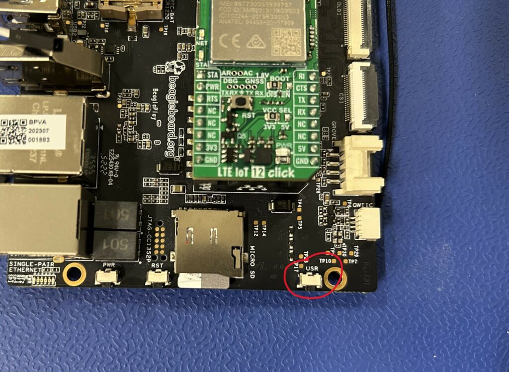
- Hold down USR button while applying power to boot from the microSD card
6. SSH into the BeaglePlay
Note: For this setup, it is helpful (but optional) to have two terminals open on the BeaglePlay when launching PPP and testing the connection with a ping. This can be done with a serial console and by ssh-ing into the board once, or with two ssh sessions.
Support for PPP is built into the Linux kernel, so there is no need to install any additional software. But the user can check which version of PPP they have with the following command.
pppd --version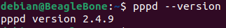
Powering on the Cell Modem
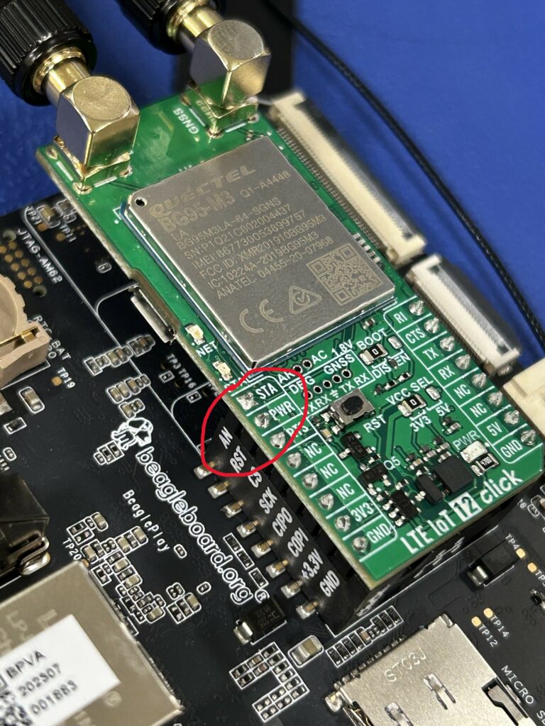
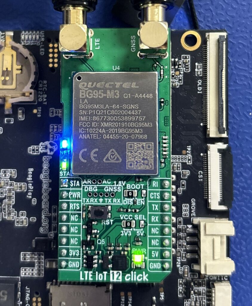
Once the board is booted and the serial console has been opened the cell modem will most likely need to be powered on. Some modem EVMs might have a push button switch. Others may have a pin that needs to be toggled. For the Quectel BG95 – it was the latter. On the board itself, there is a pin titled “PWR” that needs to be toggled through the mikroBUS connector to power the board. And a status pin titled “STA” that needs indicates the status of the board. See the BG95 hardware design for more information.
To understand how to access the hardware with the software, the user needs to look into the device tree. But first, confirm that the BeaglePlay is operating on the expected kernel version.
uname -a
If using the same Debian image used to test this setup, the output should be what is shown above.
For kernel 6.12 the device tree source (DTS) file can be found here. The DTS file did not need modifications due to the utilization of the mikroBUS standard connector. Use the ctrl+F function and search “mikrobus” to look for the pins needed. The peripherals associated with the mikroBUS connector, such as SPI, UART, and I2C, are clearly shown but there is not much more information on GPIO pins. The next step is to identify which pins on the mikroBUS header connect to the relevant pins on to the modem.

The “STA” pin on the BG95 is connected to “AN” on the mikroBUS connector and the “PWR” pin on the BG95 is connected to “RST” on the mikroBUS connector for the BeaglePlay. The RST/PWR pin needs to be toggled first. To identify which GPIO this is, look at the schematic of the BeaglePlay.

The schematic shows that “AN” is GPIO1_10 and “RST” is GPIO1_12. This can be verified with the design files in the BeaglePlay design repository.
All of the GPIOs can be listed out with gpioinfo to see naming conventions.
gpioinfo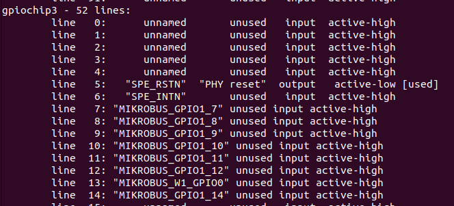
The above section is the relevant information from the output. The naming conventions of the desired mikroBUS GPIOs are MIKROBUS_GPIO1_10 and MIKROBUS_GPIO1_12. The commands for clearing, setting, and reading the pins of interest are below.
gpioset --mode=exit $(gpiofind MIKROBUS_GPIO1_12)=0gpioget $(gpiofind MIKROBUS_GPIO1_10)gpioset --mode=exit $(gpiofind MIKROBUS_GPIO1_12)=1To turn on the modem first set the RST/PWR pin as an output and clear it to 0, read the AN/STA pin, it should read as 0 since the device is off. Then set the RST/PWR to 1, when reading the AN/STA pin, it should now read 1 since the device is on. This sequence is demonstrated below.
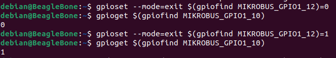
Wait a couple seconds and the blue and green LEDs on the BG95 should begin lighting up, indicating that it is on.
Establishing a Serial Connection With the Modem
The BeaglePlay will need to talk to the modem over serial commination. Typically, this is done over USB, however the mikroBUS click header does not have the USB pins broken out, so UART will be used.
To look at all the available UART ports perform the following.
ls /dev/ttyS*
Looking back at the DTS file referenced earlier, search “mikrobus_uart” to see that the UART connection on the mikroBUS click header is main_uart5. Search “main_uart5” in the DTS file to see that it is serial port 0. Serial port 0 is ttyS0, seen earlier when listing out available serial ports.
The default baud rate for modem serial communication on the BG95 is 115200. First configure this port with the below command.
sudo stty -F /dev/ttyS0 115200 cs8 -cstopb -parenb -crtsctsNow open up a serial port using your terminal emulator of choice. Tio was used here.
sudo tio /dev/ttyS0AT Commands
Once a serial connection has been established with the modem, the BeaglePlay can communicate with the modem through AT commands. AT commands are an industry standard, providing a text-based interface to the modem’s functionality. To exit serial commination, follow instructions at the top of the terminal emulator session. To learn more about AT commands and how they’re used on this modem, see Quectel’s AT commands Manual. In order for AT commands to be processed by the modem, a carriage return “\r” is required. After typing the desired command, press “enter” for it to be processed.
To test the modem is functioning properly, type in “AT” and the modem should respond with “OK” as seen below.
AT
OK
First check SIM presence and status with “AT+CPIN?” The desired response is shown below.
AT+CPIN?
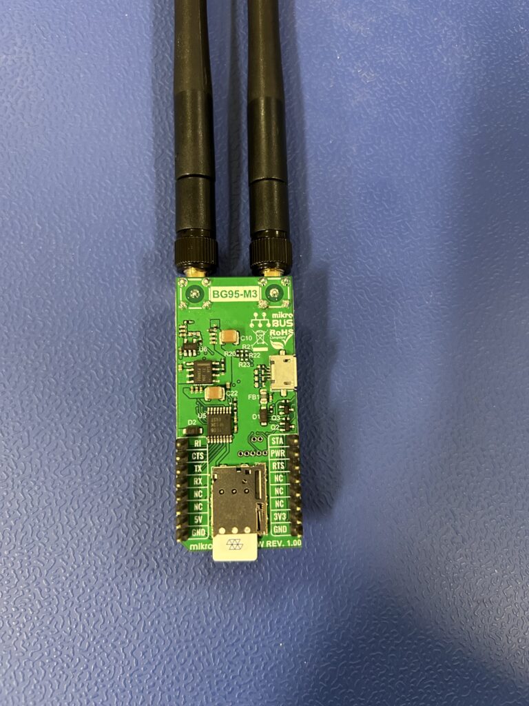
+CPIN: READYIf it says SIM PIN or SIM PUK, then the sim needs a code. If it says NOT INSERTED, the SIM may not be inserted properly. To reinsert, exit the serial terminal, power off the modem by clearing PWR to 0. and power down the BeaglePlay with “sudo halt” to remove and reinsert the SIM card. The sim card slot is on the bottom of the LTE IoT Click 12. Below shows a picture of the SIM card not properly inserted.
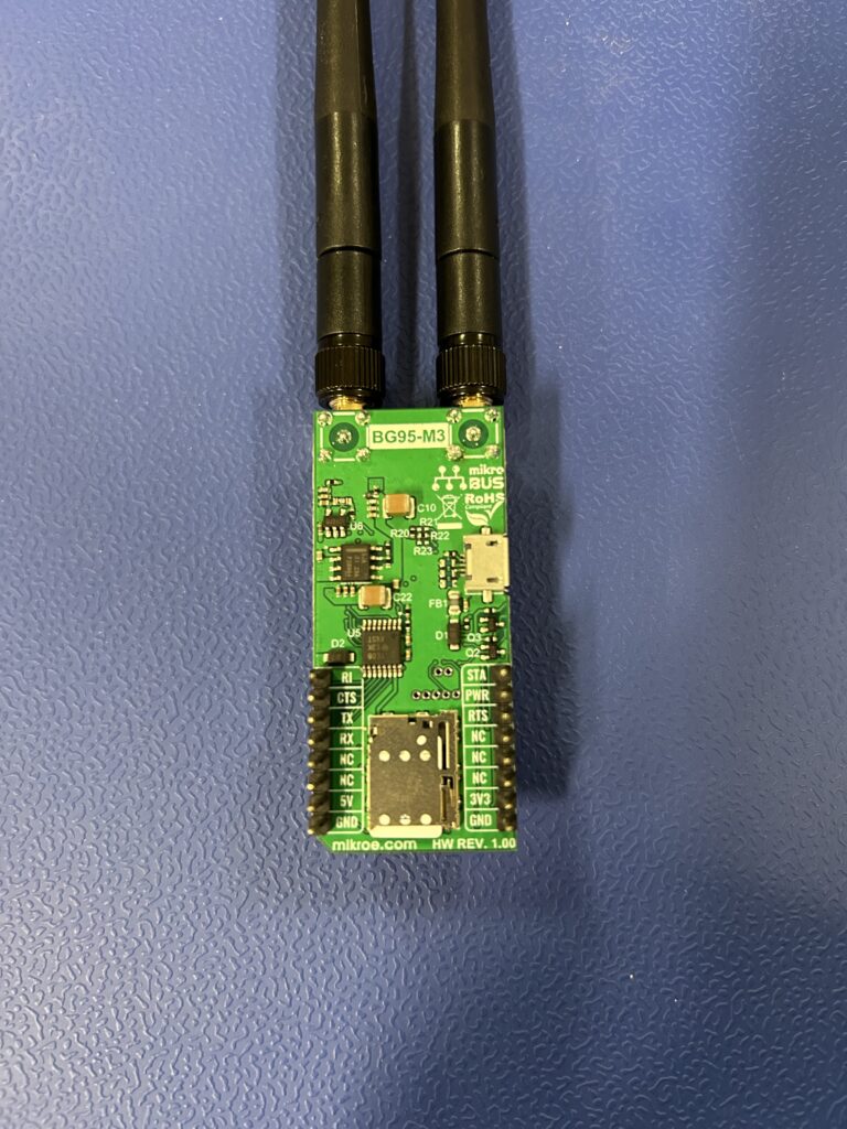
Below shows the SIM card properly inserted.
Next, check Signal Strength with “AT+CSQ”
AT+CSQ
+CSQ: 18,99
The response format is: “+CSQ: <rssi>,<BER>” where rssi is the received signal strength indication and BER is the bit error rate and reflects the quality of the signal. The value of rssi should be between 10-31 for functionality, aim for at least 15. The higher the rssi the better. A value of 99 means no signal. The value of BER is not of concern at this moment.
Next query the packet-switched network status with “AT+CEREG?”
AT+CEREG?
+CEREG: 0,5
If the response is +CEREG: x,5, then your modem is registered to a network and is roaming, which is what is needed for the next step. For a CEREG overview, look here.
Activate the Unsolicited Response Codes (URCs) for the packet-switched network status by setting CEREG to 1.
AT+CEREG=1
OK
Basically, this tells the modem to respond when the network status changes, without having to check connectivity using AT+CEREG?
Check the current network selection mode of the modem with “AT+COPS?”
AT+COPS?
+COPS: 0,0,"T-Mobile",9
For a COPS overview, look here.
Next define the Packet Data Protocol (PDP) context. The PDP context describes the settings for a packet data connection within a mobile network.
AT+CGDCONT defines the PDP including PDP type (IP, IPv6, etc.). The first parameter is the Context ID, the second is the PDP type, and third is the access point name (APN) of the operator. To see the current PDP context, type “AT+CGDCONT?” and press enter to see the current configuration.
To set up the PDP context for PPP, context, run this command, replacing “hologram” with your desired APN.
AT+CGDCONT=1,"IP","hologram"
OK
This only needs to be done once. The other tools listed in the above section can be done multiple times to verify the operation of the modem and the AT commands.
To dial into PPP, the user can type the following (WARNING: once dialing into PPP, the modem can no longer receive AT commands until it has been reset or closed the PPP session successfully. If all the commands above gave desirable outputs, it is recommended to skip ahead to the next section.)
ATD*99#
CONNECT 150000000
the modem can no longer receive AT commands, you’ve dialed PPP.
Linux Commands
Before continuing with this section, make sure the modem has not dialed into PPP and is responsive to AT commands. If the modem is not responsive to AT commands, follow the steps in the Powering on the Cell Modem section to reset the modem.
The next step is to make a script to automate the AT commands and the PPP dial up. To ensure that the serial port can be read and written to properly, optionally test UART in different terminals.
1st terminal
cat /dev/ttyS02nd terminal
echo -e "AT\r" > /dev/ttyS0After running this command in the second terminal, you should see “OK” in the 1st terminal. This verifies that you can read and write using these commands and we can now move onto creating a script to automate modem configuration and PPP dial up. If no response is seen in the 1st terminal, re-configure the serial terminal using the configuration provided in the Establishing a Serial Connection With the Modem section.
Now make two scripts, one titled “bg95” and one titled “bg95-chat.” The latter is a chat script which is often used to automate modem configuration and PPP dial up.
sudo vi /etc/ppp/peers/bg95Copy and paste the following contents into this file with ctrl+shift+v.
# This file is titled "bg95" and is inside /etc/ppp/peers

# Serial port to communicate through
/dev/ttyS0

# Speed of serial line (baud rate)
115200

# Use chat script to automate modem dial up.
connect "/usr/sbin/chat -v -f /etc/ppp/peers/bg95-chat"

# Assume ip address allocated dynamically by the ISP
noipdefault

# Try to get the name server addresses from the ISP
usepeerdns

# Use this connection as the default route to the internet
defaultroute

# Makes PPPD "dial again" when the connection is lost
persist

# Do not ask the remote to authenticate
noauth

# No hardware flow control on the serial link
nocrtscts

# No model control lines
local

# lock the serial port to avoid race conditions
lock

# Some carriers don't like async compression, disable in case
asyncmap 0

# Don't detach from the terminal
nodetach
After pasting, exit and save the contents with esc + :wq + enter.
Now make the chat script.
sudo vi /etc/ppp/peers/bg95-chatCopy and paste the following contents.
# This file is titled "bg95-chat" and is inside /etc/ppp/peers
TIMEOUT 30
ECHO ON
ABORT "NO CARRIER"
ABORT "NO DIALTONE"
ABORT "ERROR"
ABORT "NO ANSWER"
ABORT "BUSY"
"" AT
OK AT+CGDCONT=1,"IP","hologram"
OK ATD*99#
CONNECT \c
# '\c' prevents newline and allows pppd to take over immediately on CONNECT
After pasting, exit and save the contents with esc + :wq + enter.
Note: After configuring the PDP context and APN with AT+CGDCONT, there is no need to do it again. This script was made with the intention of being ran before instead of manually configuring the modem. However there is no harm in reconfiguring it here.
Call the script in 1 terminal.
sudo pppd call bg95 noipdefault nodetach debug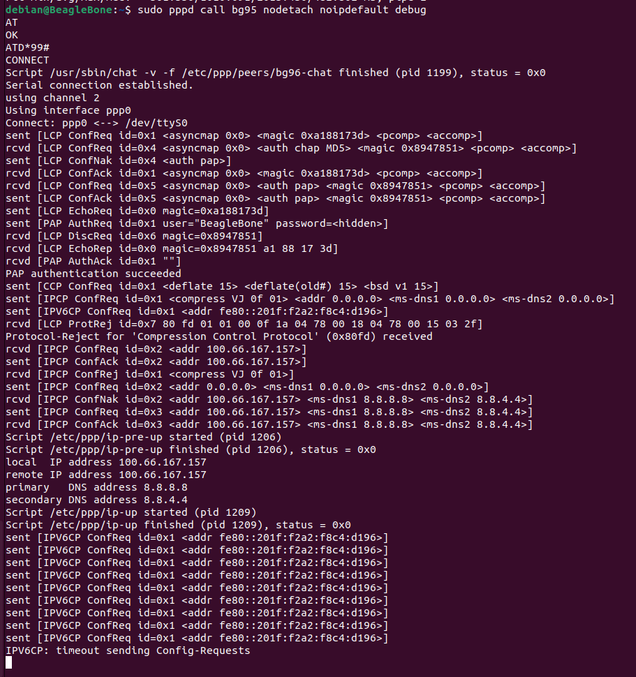
Let that connect. Now ifconfig can be used to see the ppp0 network interface.
ifconfig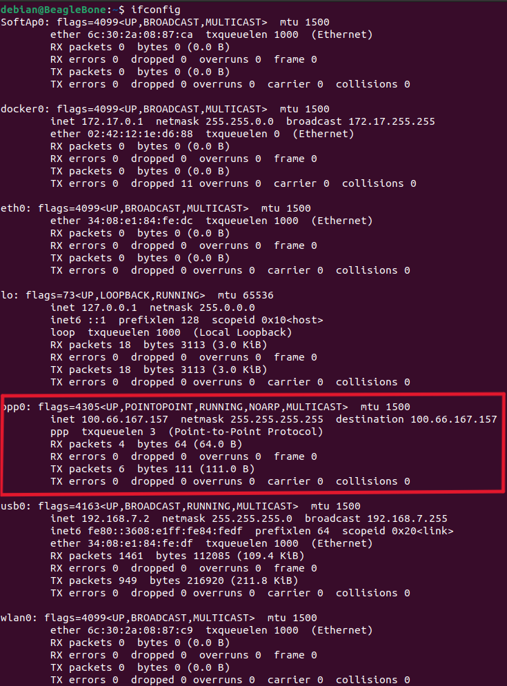
The output shoes that the ppp0 network interface has obtained an IP address indicating successful network connectivity. Now test this connectivity by pinging Google’s IP address through the ppp0 port.
ping -I ppp0 8.8.8.8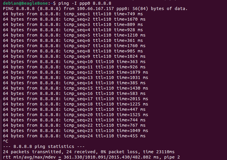
With consecutive ICMP replies and 0% packet loss, the output demonstrates that the network link is active and healthy.
Congrats! A gateway connection through a cell modem has successfully been established utilizing Point-to-point protocol.
Comments are not currently available for this post.