Categories: Advanced
We finished the
Cobra MiniSumo
chassis build in
part 1 of this project
. In order to control the bot and give it a little brain power, we sought out a
BeagleBone Black
.
The overall goal of this project was to make two robots with two controllers – one pair using the
BeagleBone Black
and one pair using the
Raspberry Pi
. We have a sumo-ring where the robots "fight", and when a bot gets knocked out of the ring, the game is over. There’s a manual control mode where you can run them around yourself – and a autonomous mode where they trace the outside of the sumo ring.
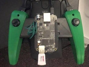
Step 1: Mounting
We moved the steel plate to underneath the bot for extra weight. We laser cut a piece of acrylic to fit as a mount for the
BeagleBone
so it can sit above the bot.
Mounting your BBB to any kind of plate above the board is pretty simple. We added four extra standoffs to allow for a little more space between the
BeagleBone
and the robot board, and four more on the top side of our acrylic plate to keep the BBB from resting directly on it.
Step 2: Wiring
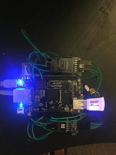
The wiring portion is fairly extensive. In addition to the
BeagleBone
, we have two
Pmods
mounted on the bot. We use the
Pmod AD2
to convert the analog signals from the sensors on the robot to digital values we can send through the BBB and eventually to
LabVIEW
.
The sensors on the robot only sense the colors white and black. The analog output reads ~1.7 V when sensing black and ~2.5 V when sensing white. The
BeagleBone
Black analog inputs have a maximum voltage reading of 1.8 V, so in order to read from the analog inputs on the board we need to step down the voltage. Using two resistors and a simple circuit (pictured above), we ran the voltage across both resistors and the SDA and SCL inputs from the
Pmod AD2
across only one resister. This made it possible for us to read the analog inputs from the robot itself without killing our
BeagleBone
.
The
AD2
has four analog inputs but in our case we only need three (because we only have three sensors). On the bot, there are three rows of inputs, each labeled PWM, DIR, W, R, and B (or some variation of these). The input labeled "R" is our analog, sensor input. Wire each analog output on the bot directly to one input on the
AD2
. The VCC on the connects to 3.3 V on the board.
The
Pmod VLSHFT
or the logic level shifter is mounted opposite of the
AD2
. The voltage is supplied by the BBB and goes into the 3.3 V input in Header J1 on the
VLSHFT
. Pin 1 and 2 in Header J1 go to DIO 7 and DIO 8 on P8 on the BBB.
We use LiPo batteries to power the bot itself, and small portable battery packs to power the board and they’re mounted below the acrylic plate.
Step 3: Controller
In order to control the bots, we built the controllers from scratch. The handles and midsection are completely 3D printed.
The controller uses two
Pmod JTSK 2s
, a
BeagleBone Black
, and a large battery pack that’s zip tied to the back. The
JSTK 2s
are wired in to the
BeagleBone Black’s
digital outputs and are supplied 3.3 V and ground from the board. We use the
Wi-Pi
to communicate to the
BeagleBone
on the bot itself.
Step 4: Programming
Our goal was to use
LabVIEW
for the entire project. You have to begin by loading
LabVIEW
onto both
BeagleBone Blacks
. There’s
a great batch of tutorials
on LabVIEW Makerhub that walk you through how to do this. The
BeagleBone Black’s
wifi is not an automatic plug-and-play either, so make sure to get wifi setup on both boards. Follow
this tutorial
to learn more about setting up wifi – we used
PuTTY
to SSH into the board and the wifi is solid.
The
LabVIEW
program is fairly extensive. We use UDP to communicate between the two boards over our router. As I mentioned before, the sensors output different voltages depending on whether or not they sense white or black.
Our sumo-ring is black with a white outline, so we have our motors shut off when any of the three sensors see white and output a voltage about 2 V. In order to re-set the game, we allow the bot to just be simply placed back into the ring, and pulling both triggers on the controller will re-set the bot.
When the bot senses any white while in autonomous mode, it’ll turn until none of the sensors output above 2 V and drive straight until it hits white again.
Step 5: The Final Product
We took our bots to NI Week and we had our sumo ring in the LabVIEW pavilion.
The sumo ring is pictured above – with a black center and white boarder. The two bots fought hard and there were many casualties, but they worked really well and they were a lot of fun to drive.
Comments are not currently available for this post.