Categories: Beginner
1. Introduction
In the days of internet of things usability and mode of deployment of devices gets more and more in the focus of customers and their corresponding needs. On the one hand the operator of a machine sits safely in a control room whereas the actual device is supposed to be deployed at a different place. Application scenarios are unmanned aerial vehicles, e. g. flying in the air or diving in water, whose mission is conducted by an operator in a control centre.
An operator’s interface can be a control panel which integrates smoothly into the application and is accepted by the operator. Its handling should be simple and intuitive but still allow the operator complex manoeuvres while being tolerant towards faulty inputs.
A potential link between the user input and the actual application needs to be arbitrary so that different transmission mediums are usable and with this wide distances coverable.
Finally an operational device is located at the end of this chain. It receives control inputs and distributes this information to robots which actually execute tasks based on these data. Potential sensor information might be fed back into the transmission line and sent back to the operator.
2. Concept Description
Based on the use case described in chapter 1 I developed a concept for this contest.
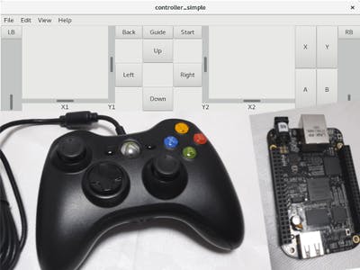
For handling user input a common game pad (Xbox360® controller) shall be used which is connected via USB to a laptop running 64bit Debian GNU/Linux. On this computer a client application shall be executed which both retrieves control signals from the game pad and holds the data link to the server application. The latter is executed for simplicity reasons on the low-cost development platform Beaglebone Black which also runs Debian GNU/Linux as operating system. Representing an operational machine a simple electronic circuit with an AVR microcontroller, an LED and USB connectivity is attached to the Beaglebone Black. It is to demonstrate reactions to user inputs with the game pad. The following figure gives an overview of the scenario just described.
The software both for the client and the server application shall be developed in Ada because the Ada toolchain could easily be installed both on the x86 x64 (laptop) and the ARM (Beaglebone Black) system.
3. Realization of the Concept
In the following the realization of the concept is described:
3.1 Transmission Medium
In this realization a network connection is set up as the arbitrary data link between client and server because, with the nowadays ubiquitous internet, arbitrary distances can be covered easily.
3.2 Client
On client side user control inputs with the game pad are retrieved and forwarded to the server application via the network data link. Furthermore the client displays control signals in a user interface. It works as a fallback system and is able to replace the game pad in case the latter is not recognized by the x86_x64 system. The consequence of these functionalities is a parallel execution of three tasks handling the data connection (environment task), input events from the game pad (controller task) and user interface (ui task). The application is terminated as soon as the user interface is closed. A functional description of this tasking as well as the corresponding sequence diagram is shown in Figure 2.
At the beginning of the client/environment task the connection to the server application is established.
In case of success the environment task retrieves data from the controller or, if the controller is blocking, the user interface. As soon as user input is available it is synchronized with the user interface and transferred via the network to the server.
Additionally the controller’s and ui’s state are checked for program termination. As soon as an application shutdown occurs both the controller and ui task are signalled to terminate and it is waited for this to actually happen. For an active controller the controller task can only terminate as soon as the controller has been hit a final time because the access to the controller is blocking. Only when controller and ui task have terminated the environment task terminates, too. Figure 3 shows the described program sequence.
The controller task starts with opening the connection to the controller. In case of success it switches to the operational state where the Xbox360® controller is checked regularly for state changes. If opening the connection to the controller fails, the tasks will wait until it is terminated. Finishing the task is done in two stages to synchronize itself with the ui task. Before the controller task terminates the connection to the controller is closed.
A similar sequence is applicable for the ui task. However instead of opening a connection, the event system is initialized. Additionally, while checking for user inputs, it is checked for program termination. These events are forwarded to the environment task. Figure 4 displays the interaction of the three tasks in a sequence diagram.
3.3 Server
On the server side the program flow is as follows: at the beginning the server is initialized and established waiting for client requests. As soon as a client request arrives both establish a connection and the server waits for controller inputs from the client which are forwarded to the custom circuit board. The program flow of the server is designed in a way that it can accept several clients one after another. Upon request a client can shutdown the server application. A sequence diagram of this program flow is shown in Figure 5.
4. Display of the Demonstrator
A demonstration of the hardware and software setup shows the following short video sequence:
5. List of Hardware Used
• one x64 computer running a 4.9.0-8-amd64 Debian distribution of x86_64 GNU/Linux for development (https: //www.debian.org/)
• one Xbox360® from the Microsoft (see
https://www.xbox.com
for details)
• one Beaglebone Black (Revision A5A) running the operating system Debian-9.2-iot-armhf-2017-10-10-4gb (www.beagleboard.org)
• one 8 MB micro SD card to extend the flash memory on the Beaglebone Black for the GNAT compiler and a bigger HOME partition
• one simple electronic circuit with an Atmega328 AVR microcontroller, an LED for displaying user interaction and USB connectivity
• several commercial-of-the-shelf parts: network cables, 5 V power supply for Beaglebone Black
6. List of Software Used
• GNAT compiler (package gnat) and GNAT Programming Studio GPS 6.1.1 (20150118) (package gnat-gps) for Ada software development installed on the x64 computer (see also www.adacore.com)
• GNAT compiler (package gnat) for Ada software development installed on the Beaglebone Black
• Glade 3.20.0 for designing the user interface
• a LaTeX typesetting system for writing this documentation
• Inkscape 0.92.1 r15371 for drawing images
Comments are not currently available for this post.