Categories: Advanced
***PLEASE NOTE: This radio must only be used by a qualified, licensed HAM radio operator***
Introduction
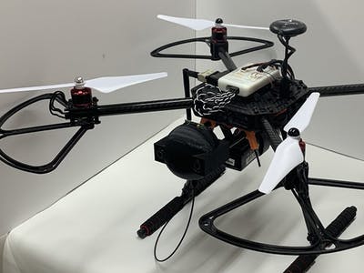
Currently many firefighter and emergency response groups must rely on fixed infrastructure communication links, or temporary field based communication repeaters which must be manually transported and installed at limited coverage (remote) locations. The availability of fixed infrastructure nodes during a disaster can be unpredictable, and temporary network hardware can be time and resource intensive to deploy in order to restore critical network routes, or add the required network coverage. Additionally, maintaining situational awareness during large-scale responses can be challenging due to the terrain and environment degrading or preventing line-of-sight communication. The Rescue Repeater, a drone-based radio repeater, allows communications to be rapidly restored or extended over the horizon.
For a proof-of-concept we chose to develop a radio that could transmit using HAM radio frequencies which are very similar to emergency communications frequencies and can use the same hardware. What makes this design special is it creates a mobile radio frequency (RF) digital repeater (digipeater) to extend the Automatic Packet Reporting System (APRS), a well-established network currently used by HAM radio operators to transmit situational awareness information and messages. This allows the use of off-the-shelf software and hardware to help develop and test this design. Adding a radio like this to a drone only enhances it’s performance with being able to provide high-altitude line-of-sight communications in environments that are typically challenging to RF signals.
This design was originally developed for the HoverGames: Fight Fire with Flyers competition with NXP and
Hackster.io
The design and project details are listed below.
Ham Radio Development
Our initial thought was to use a stripped-down hand-held radio (handie talkie – also known as an HT) for the backbone of the communications radio, but with researching the various options we came across the HamShield made by Enhanced Radio Devices. This option provided numerous benefits – it was a bare-bones PCB already, power consumption was minimal, and packaging would be much more straightforward (not to mention lighter weight) than even a stripped-down HT. While there appeared to be a handful of projects using this PCB for APRS projects already, all were land-based units. Despite this it appeared to be the ideal hardware for our project.
To communicate with the HamShield we considered both the Raspberry Pi and the BeagleBone. Ultimately it was decided to use the PocketBeagle due to its size as well as having slightly more experience programming and using the BeagleBone architecture.
As we moved further along in the development process it was determined that we needed an Arduino to act as a middleman between the HamShield and the PocketBeagle to handle the audio I/O as the libraries currently available for the HamShield to interact with the BeagleBone platform are limited but the Arduino libraries are much further developed.
A step-by-step guide on programming the radio electronics can be found in PDF form under the attachments of this project, with the wiring schematic located below.
Drone Setup
As there is extensive documentation and videos showing how to setup the NXP drone kit (part number KIT-HGDRONEK66) we will not go into detail about it here. However, some of the key (and challenging) issues we ran into and recommend to watch out for are listed below.
- Test as many components as possible before assembly
– this will help reduce the amount of tear-down and reassembly that needs to be performed - Once assembled run the drone in manual mode without any propellers
– this will enable you to see how everything works, if everything works, as well as test and verify the motors will be okay. We had one motor burn up on pretest that would have made for a hard crash landing if we hadn’t tested it first. - Verify that not only are the motors spinning in the correct direction, but they are plugged into the correct ports on the FMU
– first we would recommend testing to confirm the motors are plugged into the correct ports with the propellers still off. The easiest way we found to do this was to manual power the motors on at a low rpm and carefully pull one plug at a time to confirm the location of the motor. If the motor does not correspond to the correct port number rearrange the wires as necessary. A good image of the correct motor location can be found in NXP’s HoverGames gitbook manual under “Connecting all FMU wires”
https://nxp.gitbook.io/hovergames/userguide/assembly/connecting-all-fmu-wires.
Once the wiring for the motors has been verified mount the propellers and again power the drone manually to a low rpm, but at a speed that is fast enough to get air movement. Carefully verify that air is being pushed down below the drone under each motor. If not, turn off and remove power from the drone and swap any two wires of the three connecting to that motor to reverse its direction. Reconnect the power and try again. - The first (few) times flying, don’t use Manual mode!
– Take the time to look into the various flight options as there are quite a few to choose from. The two we would highly recommend is “Stabilized” and “Position”. - Stabilized
still gives you full control over the throttle but allows for the drone to compensate and level the drone during liftoff and flight. This also provides a good way to test that the drone will fly okay the initial time – as throttle is slowly applied you should see the drone self-right itself as the power is slowly increased. If you see the drone start to lift only on one side or shift strongly in one direction this means that either a setting or the motor setup is not correct. Power down and evaluate. - Position
mode allows the drone to compensate and automatically adjust itself to keep it in one position (including altitude). However, this can only be used if GPS location is accurate enough. The other factor to be aware of is once power is applied the drone will automatically increase RPM up to the pre-programmed hover RPM and you will not have the ability to slowly increase the motor speed. This can be quite startling the first time it happens!
Mechanical Housing
The housing for radio electronics was designed using Autodesk Inventor and printed using a Creality Ender3 3D printer. The thought behind the initial housing for the radio electronics was to place the electronics in a way that would minimize needing to remove them for debugging purposes, as well as limiting the connection needed to have the radio antenna mounted vertically to minimize any signal degradation. The housing was intentionally made large to provide extra volume and weight to account for future sensors and electronics to be added to the volume without needing to completely rework our power supply and center of gravity.
The critical features needed in the housing were slots to prevent motion of the PCBs during flight, a clearance hole for the SMA connector for the antenna, and mounting holes for attaching the housing onto the drone structure. Originally the holes were intended to be made for a tight slip-fit over the carbon fiber tubes but it was decided that allowing clearance for rubber grommets between the rods and the printed housing would provide isolation from any vibrations from the drone.
Additional files can be found at
Thingiverse: Rescue Repeater
Testing/Verification
Both the radio and drone were bench tested separately to verify functionality and make troubleshooting easier to perform. At this time we have confirmed that the radio can both transmit and receive APRS data as designed, and the drone is capable of flight with the addition of the radio housing and components.
Future Work
Drone Integration
Now that both the drone and radio electronics have been proven out, further integration into the drone electronics is needed. This includes being able to remotely control power to the radio from the drone flight control, relaying GPS data from the already incorporated GPS unit, and providing any radio adjustments needed while in flight. Future additions can include providing commands to the drone through the radio communications itself. This can be used for allowing responders using the repeater to make manual adjustments to account for environmental factors not known or seen from the base station, to providing control or a controlled decent if the signal is lost from the base station.
Software
From the start of this project one of the goals was to be able to use data provided from the drone and radio repeater to create an RF map of signal strength to position the drone in the best location relative to the responders using the repeater. Now that the basics have been worked out this will be investigated and developed further.
Mechanical
While the housing has provided a relatively quick way to support the electronics and provide the space needed, future improvements to the housing will include a removable cover plate to more easily access the electronics without having to fully slide parts in and out. A mechanical means to release and retract the antenna would also be beneficial primarily for ease of transport and landing.
About the Creators:
Doug Brummund
dbrummund@brummundtechnologies.com
Doug, KB1MHD, has been a licensed HAM radio operator since 2005. Currently holding a General class license, he enjoys building/designing radio and electronics equipment and experimenting with digital modes, wireless networking and RF propagation. He also does some embedded programming and looks for opportunities to apply DSP and other cutting edge technologies to traditional RF hardware architectures.
Neil Whitehouse
nwhitehouse@cscprototyping.com
Neil, KB1HXV, has had his HAM radio Technician license since 2002. With a mechanical engineering background, he has continued to expand his knowledge with electronics and microprocessors with various prototypes and designs he has created over the years. Highly skilled in creating conceptual designs and working prototypes, he thrives on projects where he can use new and innovative approaches.
HoverGames
NXP
Hackster.io
HamShield
RescueRepeater
Comments are not currently available for this post.