Categories: Intermediate
Hello,
Every since seeing this idea and wanting to test the thermal imagery on the BBAI from beagleboard.org, I set out to wait, save funds, and while waiting is when I learned about different technologies.
I have had to wait a bit b/c of the cost of the FLIP camera by itself but finally-finally.
First things first:
https://drive.google.com/file/d/15rPc4huDpel8eSucpviEp-AEXx86UiSv/view?usp=sharing
is the required paperwork on the FLIR camera, datasheet of the breakout, and other informative paperwork.
So, w/out further ado, here we go.
…
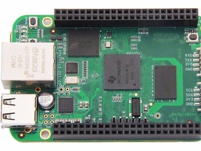
The board is a BeagleBone Green. Per the instructions, it is stated that the BBB (BeagleBone Black) and the BBG (BeagleBone Green) can be used on this project.
If you are looking to make other boards work with this specific instance of thermal imagery, more power to you!
…
So, first, let us deal with hardware. The camera and FLIR Lepton v2 module need to be purchased. Purchase a BBB/BBG. Get a bunch of jumper wires, i.e. all kinds, Male-Male, Male-Female, and Female-Female. Oh and here are some links for the correct hardware, i.e. the hardware that I used is being called correct here!
https://www.digikey.com/short/438d4w
FLIR Camera
https://www.digikey.com/short/438dmq
FLIR Camera Module with Socket/Dev. Kit (I did actually use another module but this one works too from what I hear)
https://www.digikey.com/short/438dmv
BeagleBone Green
https://www.seeedstudio.com/5-Inch-Seeed-Studio-BeagleBoner-Green-LCD-Cape-with-Resistive-Touch.html
5" LCD Cape for BBG
…
Here are some places to get the source and "applications."
Used Distro:
https://beagleboard.org/latest-images
Use the IoT and add your own source to the Distro would be a nice thing for people who want customizations!
FLIR SDK from GroupGets:
https://github.com/groupgets/LeptonModule
Now, instructions:
Okay…we need to hook up our hardware to the BBB/BBG. In my case, I used the BBG and a Lepton v2 module from
DigiKey.com
instead of the GroupGets modules from digikey.com.
So, Get that awesomely, expensive FLIR camera and gently place it in your socket on the FLIR module you have purchased. Groupgets has some available on
DigiKey.com
and there are others.
Now, we need to do some tests, run some source, check some source, and apply some basic hardware to hardware functionality.
Okay. Let us now, since the FLIR camera is attached well in its socket, pay attention to the wiring.
W/out the board attached to power, perform the steps below to handle the hardware, please.
We will need the VDD_ADC, GNDA_ADC, and all AIN pins (0 – 6) for analog usage for this specific Cape but you could prove me incorrect by doing some research, i.e. I am sure of it.
So, from your BBB/BBG, attach the P9_32 pin, which is VDD_ADC, to the same pin on your LCD Cape. Do not attach the Cape to the BBB/BBG. This is a lot of work that is fun, educational, and promotes a nice ending (hopefully).
Okay, so P9_32 to P9_40 all get attached to the same pins as though the Cape was attached but w/out attaching the Cape. So, Four Pins away on the odd numbers from the bottom of the board is AIN0 or as it is called also, P9_32.
Now, we have all our pins attached to the exact same pins they would have been attached to if the cape was on the board. Since it is not, we can move on.
Do the same for all LCD pins. So, P8_27 to the last P8 pin on P8, which is P8_46, will have to be connected via jumper wires to the Cape from the BBB/BBG.
So now, we should have the LCD pins and ADC pins attached. We are a few steps closer already.
Also…we will need to attach the 3.3v pin on the BBB/BBG to the LCD. We will also need to GND this LCD to the BBB/BBG on the P9.1 pin or P9.2 pin.
Below you will find some SPI ports, i.e. two of them to be precise.
We are going to use SPI0.0 on the BBB/BBG. Remember this for later and now we can attach our SPI port pins to the additional hardware we have found to handle the FLIR camera Lepton v2 or GroupGets modules. Oh. One side note here…in case you are fooled by now, the GroupGets modules, I am pretty sure, that I am not using right now, are USB based. They do not need to be attached via the P9 and P8 headers on the BBB/BBG. They would simply be attached via USB. I think one or more of their modules has extra port/pin availability for people looking to do more with their modules.
Here, above, we can see the SPI Chip Select, SPI MISO, SPI MOSI, and SPI Clock. Many times, you will find that Chip Select is called cs, /cs, and sometimes it has a bar above the cs. Anyway, we are using all just in case we plan on making some ‘improvements’ to the already kosher SDK.
Some homework and changes will need to be made in the SDK but I will leave that up to you! Homework!
So, now is when we should have looked over some of their SDK, gathered the materials, and have done some hardware additions to the BBB/BBG, e.g. add the jumper cables to the Resistive touch display from the BBB/BBG and the, in my case, SPI port from BBB/BBG to the Lepton v2 module, and finally make sure everything is grounded and powered w/ 3.3v and GND.
Here are some ideas on putting SPI ports to use:
https://www.analog.com/en/analog-dialogue/articles/introduction-to-spi-interface.html#
That above link will take you to a website that has some basics on SPI and hardware.
And here is where some wiki business goes down. Enjoy!
https://wiki.seeedstudio.com/BeagleBone_Green/
https://wiki.seeedstudio.com/Seeed-Studio-BeagleBone-Green-LCD-Cape-with-Resistive-Touch/
(I used the 5" LCD on this page)
https://www.cplusplus.com/doc/tutorial/
Also a good place for learning a language, C++
https://groups.google.com/g/beagleboard
This is a good source for community engagement!
Please use this command to update/upgrade:
sudo apt update && sudo apt upgrade
.
Please use this command to get the required source for promotion of Qt application we are going to use:
sudo apt install build-essential qt4-dev-tools
Also, we need to clone some repos for testing and getting the SDK:
git clone
https://github.com/derekmolloy/exploringBB
- Go to /chp08/spi/ and there is where you will find the spidev_test program to test your SPI port(s).
git clone
https://github.com/groupgets/LeptonModule
- SDK
git clone
https://github.com/beagleboard/bb.org-overlays
- cd bb.org-overlays
- This will not be needed unless you are using a 7" display version…
**********************************************************
Please remember to get some, if only using the IoT image from beagleboard.org, small, lightweight GUI instead of just using the server type.
GUIs are needed in this respect on the LCD to display. There are instructions for slim and openbox. I used xfce4 but there are many for displaying GUIs.
**********************************************************
So, just for some coolness here, the BBB/BBG will handle everything, i.e. LCD and module for the FLIR camera.
Now, we should have some hardware completion, done more work on the SDK, and we are ready to plug in the power to create a couple ideas known.
While powered, we need to test spidev_test on the BBB/BBG. This will make sure we have the correct set up done properly. Also, while plugged in, we need to set up the overlay!
So, in /boot/uEnv.txt, add the overlay for your SPI device, e.g. 0.0, 1.0, 0.1, and/or 1.1.
reboot or sudo shutdown -h now will shutdown gracefully.
Now that the overlay is attached to the file in question, let us preform some other functionality.
We should have cloned, w/ git, Molloy’s Book online. Now, we can run the source to make sure we have the correct overlay and functioning SPI device.
so, ./spidev_test is the command in /chp08/spi/
You can run it and expect to get back some values. Towards the end of those values are something about BE EF. Make sure you are not receiving straight 00 for every entry in your output from the spidev_test program he made.
If you are receiving the 00 00 00 and etc…
Please rewire accordingly or look through his source to understand what is going in in it. Pay attention to every little detail. Not all source works as it is meant for specific instances that may have nothing to do w/ the BBB/BBG.
Altering source is normal and it comes in handy to know how when it is time to do so…
Seth
P.S. Once we are connected via jumper wires and have everything set up correctly, view this video to see the output on the LCD from the eewiki instructions for use w/ the BBB/BBG, LeptonModule, and FLIR camera!
Oh!
SPI is ‘more complicated’ than asynchronous buses like UART in that it takes a synchronous couple or more signals. It is not dedicated to one line for communication one way, i.e. like w/ a UART move from TX from one peripheral to the next RX on another peripheral.
Although, my depth on this subject is starting out low, I plan on reading more as time passes. Here is a good starting point and you can learn in general a lot from SparkFun people and their tutorials:
https://learn.sparkfun.com/tutorials/serial-peripheral-interface-spi/all
.
…
https://www.sparkfun.com/spi_signal_names
is the change from MOSI/MISO to the new effort in name resolution. Here is another good source from the ‘authority.’
…
https://www.oshwa.org/a-resolution-to-redefine-spi-signal-names/
is the Open Source Hardware Assoc. website that describes similarly what was described on the SparkFun website…
So, it seems that some inconsistencies in belief dedicated to practice of SPI devices needed a new label for the device. So, it has been done. Now, instead of MOSI, which we all know what it means, is now COPI (Controller Out, Peripheral In). Let me know what you think. In the world of BLM, riots, and up-to-date, politically correct phrasing, this is a resolution. Plain and simple! I think w/out the rhetoric and dysfunction, the resolution is just fine. Now, we can all join our cohorts in programming while not offending anyone in this country or other countries. Nice!
Also…there is a nifty plantspy application online that I found here:
https://github.com/sentient-controls/plantspy
. If you are willing to put in some work and change out some of the items in the source, make the required library installs, and make the correct wiring, you can get this OpenCV and FLIR Lepton v2 lib. working.
The lib. was for plants at first but you may be able to help me finish this person’s work or at least use the source to make OpenCV account for different things in your Camera from FLIR.
use ./plantspy_live.py and adjust accordingly, i.e. as I, w/ the BBB/BBG, could not get the regular
plantspy.py
file working w/out some alterations that I know nothing about.
Here:
You will need pylepton, the plantspy source, and make changes in the source on the plantspy source to suit your needs. I will update sooner than later on the way to alter the source on plantspy_live.py so that things can be easier on the reader instead of pure homework!
Comments are not currently available for this post.