Categories: Intermediate
About BBBmini
BBBmini is an autopilot / flightcontroller Cape for the BeagleBone Green. BBBmini + BeagleBone Green can be used as a state of the art Linux autopilot / flightcontroller for Copter, Planes or Rovers. BBBmini can be used with
ArduPilot
(open source unmanned aerial vehicle flight stack. BBBmini is a DIY project using widely available IMU and barometer breakout sensor boards, there is no SMD soldering necessary. The design is made that everybody can build a BBBmini by himself. In flight internet connection is done via WiFi link.
What does BBBmini offer:
- DIY state of the art UAV autopilot / flightcontroller
- Easy to build, no SMD soldering necessary
- Free hardware, free software
- Autopilot / flightcontroller software is running on Real-Time Linux
- DIY friendly connectors 0.1” pin header
- 12 x PWM out with individual frequency for each channel
- RC in connector for PPM, S.BUS or spektrum satellite input
- MPU-9250 IMU 9 x DOF
- MS5611 barometer
- HC-SR04 ultrasonic rangefinder
- GPS for full autonomous flights
- Voltage and current sensing
- I2C / GROVE connector for Status display and additional sensors
- SPI connector for second redundant IMU
- U
ART / GROVE connector for GPS
- UART / GROVE connector for telemetry
- CAN connector with on board CAN bus transceiver
- USB connector used for WiFi, Laser rangefinder or cameras
- Excellent cost-performance ratio
The BBBmini project development includes:
- BBBmini documentation / how to
- BBBmini PCB design done with
Kicad
all sources free available on
Github - Device tree file for BBBmini hardware
- PRU firmware: 12 x PWM OUT with better than 1us accuracy, separate frequency for each channel. RC input capture with 5ns accuracy, can be used to capture PPM, S.BUS or spektrum satellite
- PRU firmware: HC-SR04 Ultrasonic Rangefinder device driver
- Commits to ArduPilot project to get BBBmini supported by ArduPilot
- Development of status display device driver for ArduPilot
- Add redundancy sensors via SPI / I2C or UART
- Lots of test flights and fine tuning in hardware and software to get a stable and reliable BeagleBone Green flightcontroller
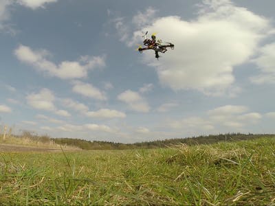
See the BBBmini flying
Why BeagleBone Green
Once I had the idea to develop an flightcontroller, I have examined on the market available computer for their suitability. The following criteria should be met by the computer being used.
First, the computer should be very well supported by the community. As a result, a Raspberry Pi or BeagleBone could be used.
In addition, the flightcontroller should be set up with as little as possible external components.
The decision was made for the BeagleBone. With the Programmable Real-Time Units of the BeagleBone, it is possible to create the BBBmini with only a few sensor breakout boards. In addition the BeagleBone offers many interfaces such as UART, SPI, I2C, CAN, USB and ADC. All these interfaces are used by the BBBmini.
BeagleBone Green parts used for BBBmini
- Main CPU running Linux
- PRU0 device driver for HC-SR04 ultrasonic rangefinder
- PRU1 to generate 12 PWM signals and receive PPM, S.BUS or spektrum satellite input
- Grove / I2C for communication to the status display, external compass or Laser rangefinder
- GROVE / serial 2 for sensors like Laser Rangefinder
- Serial 4 for telemetry radio
- Serial 5 for GPS
- ADC for voltage and current sensing
- SPI1 for high speed data transfer from IMU and Baro sensor
- SPI0 for high speed data transfer from second redundant IMU or other hardware
- CAN for communication with ESCs and additional hardware
- USB for WiFi and camera connection for life HD video transmission
- Ethernet for communication on ground
Assemble BBBmini
Step 1:
Solder resistor R4 and R5.
For 3.3V RC input signal use R4 = 0Ω (bridge) and R5 = open (see picture)
For 5V RC input signal use R4 = 1kΩ and R5 = 2kΩ
Step 2:
Solder resistor
R1 = 120Ω
R2 = 1kΩ
R3 = 2kΩ
R6 = 20kΩ 0.1%
R7 = 10kΩ 0.1%
R8 = 20kΩ 0.1%
R9 = 10kΩ 0.1%
to the bottom layer.
Step 3:
Solder CAN transceiver on the top layer
Step 4:
Solder male pin-header on top layer
P1, P2, P3, P4, P7, P10, P11, P12, P13, P14, P15, P16, P17, P18, P19, P20, P21
Step 5:
Solder C1 and C2
Step 6:
Solder female pin-header P5 and P6 on top layer
Step 7:
Solder male pin-header P8 and P9 to bottom layer
Step 8:
Solder male pin-header to bottom layer of GY-9250 and GY-63
Step 9:
Mount spacer to BBBmini
Step 10:
Mount GY-9250 and GY-63
Finish! BBBmini is ready to use for Copter, Planes or Rover.
Prepare BeagleBone Green
Prepare microSD with your host computer
Step 1:
Download Debian image to host computer
wget https://rcn-ee.com/rootfs/bb.org/testing/2016-03-13/console/BBB-eMMC-flasher-debian-8.3-console-armhf-2016-03-13-2gb.img.xz
Step 2:
Decompress image
unxz BBB-eMMC-flasher-debian-8.3-console-armhf-2016-03-13-2gb.img.xz
Step 3:
Copy image to microSDcard (>= 2GB)
/dev/sdX point to your microSD, be careful here!!! Use
lsblk
to figure out, which is your mircroSD. The process can take 15-30 minutes depending on the speed of your microSD card.
sudo dd bs=4M if=./BBB-eMMC-flasher-debian-8.3-console-armhf-2016-03-13-2gb.img of=/dev/sdX
Step 4:
sync
and remove microSD
sync
Install Debian to your BeagleBone eMMC
Step 1:
Plug prepared microSD into BeagleBone
Step 2:
While holding down the boot button, apply power to the board. If there is a newer Debian installed, holding down the boot button is not necessary.
Step 3:
Wait some minutes until Debian is installed (all four LEDs turned on).
Step 4:
Remove power.
Step 5:
Apply power again.
Step 6:
Connect to the BeagleBone (password =
temppwd
)
ssh debian@beaglebone
Step 7:
Update Software
sudo apt-get update && sudo apt-get upgrade -y
Step 8:
Install software
sudo apt-get install -y cpufrequtils g++ gawk git make ti-pru-cgt-installer device-tree-compiler screen python
Step 9:
Update scripts
cd /opt/scripts && sudo git pull
Step 10:
Install RT-Kernel
sudo /opt/scripts/tools/update_kernel.sh --bone-rt-kernel --lts-4_1
Step 11:
Add BBBMINI DTB
sudo sed -i 's/#dtb=$/dtb=am335x-boneblack-bbbmini.dtb/' /boot/uEnv.txt
Step 12:
Adjusting the BeagleBone clock
sudo sed -i 's/GOVERNOR="ondemand"/GOVERNOR="performance"/g' /etc/init.d/cpufrequtils
Step 13:
Reboot system
sudo reboot
Step 14:
Login again
ssh debian@beaglebone
Step 15:
Clone overlays
git clone https://github.com/beagleboard/bb.org-overlays
Step 16:
Change dir
cd ./bb.org-overlays
Step 17:
Update DTC
./dtc-overlay.sh
Step 18:
Build and install overlays
./install.sh
Step 19:
Add ADC DTBO
sudo sed -i 's/#cape_enable=bone_capemgr.enable_partno=/cape_enable=bone_capemgr.enable_partno=BB-ADC/g' /boot/uEnv.txt
Step 20:
Reboot system
sudo reboot
Step 21:
Login again after reboot
ssh debian@beaglebone
Step 22:
Clone ArduPilot sourcecode
git clone https://github.com/diydrones/ardupilot.git
Step 23:
Change dir
cd ardupilot
Step 24:
Init submodule
git submodule init
Step 25:
Clone submodule
git submodule update
Step 26:
Change dir
cd Tools/Linux_HAL_Essentials/pru/rangefinderpru
Step 27:
Build Rangefinder firmware
make
Step 28:
Install Rangefinder firmware
sudo make install
Your BeagleBone is now ready to use.
Build ArduPilot software
BBBmini uses
ArduPilot
as flight stack. I contribute patches to the ArduPilot that BBBmini is supported by
ArduPilot
software.
Compile ArduPilot native on BeagleBone
Step 1:
cd ardupilot
Step 2:
alias waf="$PWD/modules/waf/waf-light"
Step 3:
waf configure --board=bbbmini
Step 4:
(take about 1h20)
waf
Step 5:
cp build/bbbmini/bin/* /home/debian/
Cross compile ArduPilot (faster)
To compile ArduPilot for BeagleBone on an Ubuntu computer the following packages are required:
sudo apt-get install git gawk g++-arm-linux-gnueabihf
Get the source code and build ArduPilot:
Step 1:
git clone https://github.com/diydrones/ardupilot.git
Step 2:
cd ardupilot
Step 3:
git submodule init
Step 4:
git submodule update
Step 5:
alias waf="$PWD/modules/waf/waf-light"
Step 6:
waf configure --board=bbbmini
Step 7:
waf -j8
Step 8:
scp build/bbbmini/bin/* debian@beaglebone:/home/debian/
BBBmini Test
For safety reasons dismount all propellers when testing BBBmini.
Step 1:
Check connection to sensors
1. Connect BeagleBone Green via Ethernet to Network
2. Supply power to the BBBmini
3. Connect to BeagleBone Green from host computer with ssh
ssh debian@beaglebone
4. Start arducopter
Parameter description:
-B /dev/ttyO5
GPS connected to serial port 5
-C /dev/ttyO4
telemetry radio connected to serial port 4
sudo ./arducopter-quad -B /dev/ttyO5 -C /dev/ttyO4
5. Check if startup is successful
nit APM:Copter V3.4-dev


Free RAM: 262144


FW Ver: 120


----------------------------------------


load_all took 210us


0 0 0 DataFlash_File: buffer size=16384


� Q}�HMC5843: Could not detect version


� Q��Init Gyro*� Q� ***


Ready to FLY
The output should look like this.
HMC5843: Could not detect version
does not matter, because there is not a HMC5843 connected. The non ASCII symbols are MAVLink messages, that is alright.
Step 2:
Add arducopter to automatic start at boot time
1. Edit rc.local
sudo nano /etc/rc.local
2. Add automatic arducopter startup
Parameter description:
-B /dev/ttyO5
GPS connected to serial port 5
-C /dev/ttyO4
telemetry radio connected to serial port 4
#!/bin/sh -e

#

# rc.local

#

# This script is executed at the end of each multiuser runlevel.

# Make sure that the script will "exit 0" on success or any other

# value on error.

#

# In order to enable or disable this script just change the execution

# bits.

#

# By default this script does nothing.

/home/debian/arducopter-quad -B /dev/ttyO5 -C /dev/ttyO4 &

exit 0
Save and exit: Strg + o and Strg + x
Setup BBBmini Quadcopter
Step 1:
Assemble frame
Step 2:
Connect motors and ESC
Step 3:
Connect power distribution
- Connect each ESC to the power distribution board
- Connect the 5V power distribution board output to BBBmini P11 power input
- Connect the voltage and current sensing power distribution board output to BBBmini P21 voltage and current sensing pins
Step 4:
Connect RC receiver
Step 5:
Connect display
Connect your SSD1306 OLED display to P15 or I2C GROVE port
P15 or GROVE +3.3V to display VCC
P15 or GROVE GND to display GND
P15 or GROVE SDA to display SDA
P15 or GROVE SCL to display SCL
Step 6:
Connect GPS
Connect your GPS to P10.
P10 +3.3V to GPS VCC
P10 GND to GPS GND
P10 RX to GPS TX
P10 TX to GPS RX
Step 7:
Connect telemetry
Connect your telemetry radio to P7.
P7 +5V to telemetry radio VCC
P7 GND to telemetry radio GND
P7 RX to telemetry radio TX
P7 TX to telemetry radio RX
Step 8:
Connect HC-SR04
Connect your HC-SR04 ultrasonic rangefinder
P19 +5V to HC-SR04 VCC
P19 GND to HC-SR04 GND
P19 TRIG to HC-SR04 TRIG
P19 ECHO to ECHO TRIG
Check / configure BBBmini
Plug USB telemetry radio into your host PC. I recommend to use
APM Planner
ground control station for beginners. Advanced user can use
MAVProxy
ground control station.
Step 1:
Start APM Planner
Step 2:
Change serial port to USB telemetry radio serial port
Set baudrate to 57600
Press connect button, wait for connection established
Wait some seconds to load parameters from BBBmini
Step 3:
Move BBBmini and check that Primary Flight Display is moving too
Step 4:
Switch to
INITIAL SETUP
Step 5:
Switch to
COMPASS
Hit button
Live Calibration
Move BBBmini in all axis until calibration is completed
Step 6:
Switch to
Accel Calibration
Hit button
Calibrate
and follow instructions
Step 7:
Switch to
Radio Calibration
Hit button
Calibration
and follow intructions
Step 8:
Switch to
Flight Modes
Setup that you are able to switch between
Stabilize
,
Loiter
and
RTL
First Flight / Drive
Be sure all test are successful. Read and follow the
safety instructions
.
Because I did a lot of contributions to the
ArduPilot
project, BBBmini is full supported by
ArduPilot
software. Check
ArduPilot website
for instruction how to setup and use an
ArduPilot
autopilot. The
ArduPilot
website will provide you with all necessary information about how to build and fly (drive) vehicles with your BBBmini.
Links:
Support
If you have questions about you BBBmini you can join the BBBmini user group on
diydrones.com
or ask for support at the gitter BBBmini support chat.
Links:
Dual IMU (optional)
You can connect a second GY-9250 IMU to the BBBmini.
Setup 5GHz WiFi (optional)
Using USB WiFi with Linux can be complicated because of missing support of the WiFi chip by the Linux Kernel. It is very important to select a well supported WiFi USB stick. One of these are Ralink RT5572 based WiFi USB sticks. They can transmit at 2,4GHz or 5GHz. It is not necessary to compile a driver, it is supported by the Linux Kernel out of the box. With the Debian we use for the BBBmini you only have to install the firmware and some tools for the RT5572 chip with:
sudo apt-get install firmware-ralink crda wpasupplicant wireless-tools
Here is a list with RT5572 based WiFi USB sticks.
You have to configure your location because the restrictions of the frequency usage depends of the country where you use the WiFi stick. For me it is DE for Germany. Replace
DE
to your country code.
sudo sed -i "s/REGDOMAIN=/REGDOMAIN=DE/g" /etc/default/crda
Edit your WiFi configuration:
sudo nano /etc/network/interfaces
auto wlan0

iface wlan0 inet dhcp

wpa-ssid "essid"

wpa-psk "password"
Save and exit with Strg + O and Strg + X
You can use WiFi to control your BeagleBone Green Linux, telemetry link or / and Live video transmission.
Live video transmission with BeagleBone Green and BBBmini (optional)
What additional components you need for live video transmission:
- USB HUB
- USB camera with hardware H264 support
- USB WiFi dongle
I use this H264
camera
with success with my BeagleBone Green (
Link
).
Install required software:
sudo apt-get install gstreamer1.0-tools gstreamer1.0-plugins-good gstreamer1.0-plugins-bad
Start video transmission:
gst-launch-1.0 v4l2src device=/dev/video1 ! video/x-h264,width=640,height=360 ! h264parse config-interval=1 ! rtph264pay ! udpsink host=192.168.178.25 port=5000
Change
192.168.178.25
to our host computer IP address.
Performance:
With ArduPilot running and video streaming the BeagleBone Green has a CPU load of about 25%.
Receive video transmission on Linux host computer:
gst-launch-1.0 udpsrc port=5000 ! application/x-rtp, encoding-name=H264,payload=96 ! rtph264depay ! h264parse ! avdec_h264 ! autovideosink
Safety
Always follow this safety instructions.
License
BBBmini by Mirko Denecke is licensed under a
Creative Commons Attribution-ShareAlike 4.0 International License
.
UNLESS OTHERWISE MUTUALLY AGREED TO BY THE PARTIES IN WRITING, LICENSOR OFFERS THE WORK AS-IS AND MAKES NO REPRESENTATIONS OR WARRANTIES OF ANY KIND CONCERNING THE WORK, EXPRESS, IMPLIED, STATUTORY OR OTHERWISE, INCLUDING, WITHOUT LIMITATION, WARRANTIES OF TITLE, MERCHANTABILITY, FITNESS FOR A PARTICULAR PURPOSE, NONINFRINGEMENT, OR THE ABSENCE OF LATENT OR OTHER DEFECTS, ACCURACY, OR THE PRESENCE OF ABSENCE OF ERRORS, WHETHER OR NOT DISCOVERABLE. SOME JURISDICTIONS DO NOT ALLOW THE EXCLUSION OF IMPLIED WARRANTIES, SO SUCH EXCLUSION MAY NOT APPLY TO YOU. EXCEPT TO THE EXTENT REQUIRED BY APPLICABLE LAW, IN NO EVENT WILL LICENSOR BE LIABLE TO YOU ON ANY LEGAL THEORY FOR ANY SPECIAL, INCIDENTAL, CONSEQUENTIAL, PUNITIVE OR EXEMPLARY DAMAGES ARISING OUT OF THIS LICENSE OR THE USE OF THE WORK, EVEN IF LICENSOR HAS BEEN ADVISED OF THE POSSIBILITY OF SUCH DAMAGES.
Comments are not currently available for this post.