Categories: Intermediate
The movement generated by earthquakes consists of a vibration on the surface of the earth whose direction contains the three spatial components: two horizontal and one vertical. This vibratory movement, which is currently measured with precise equipment of seismometers and accelerometers, produces inertial forces that shake buildings horizontally and vertically, and in some cases rotation forces are also generated that further complicate the behavior and stability of the structure. structure.
Likewise some details of adverse factors that appear in the buildings when an earthquake or collapse occurs due to engineering errors and that if they were taken into account who was: Architect, builder, structuralist, owner, would have prevented the collapse of said building and the collateral aggravating as: Lost of lives, wounded, monetary losses and even the pains and sufferings that these events bring to human beings.
Introduction
Due to the problems that I have just mentioned, taking into account the consequences that structural collapses entail, such as loss of life, injuries, economic losses, domestic calamity among others; There is an urgent need to design a monitoring system that has the capacity to measure and record any structural movement to prevent these consequences.
That is why we will build a monitoring system controlled by an Arduino UNO and more importantly will have the new 3D Magnetic Sensor 2Go TLE493D A2B6 from Infineon that has an accurate measurement system. All the information registered in the columns of the buildings will be interpreted in the Microsoft Excel 2016 application, Data Streamer.
Basic Scientific Terms
- earthquake
: a sudden movement of the earth’s crust caused by the release of stress accumulated along geologic faults or by volcanic activity
- epicenter
: the point on earth’s surface that is vertically above the focus of an earthquake
- focus
: the point of origin of an earthquake
- longitude
: part of a grid used for describing positions on the earth’s surface, consisting of half circles joining at the poles. A measurement, in degrees, of a place’s distance east of west of the prime meridian, which runs through Greenwich, England.
Basic Hardware Terms
- 3D Magnetic Sensor 2Go
: Is a 6-pin 3.3V I²C magnetic field and temperature sensor. The 3D Magnetic Sensor 2GO Development Kit contains the TLE493D (magnetic field sensor), the XMC1100 microcontroller (
datasheet)
, the XMC4200 microcontroller (
datasheet)
, and a micro USB port.
Step 1: Design and Sketch
Step 2: Required Components
To make this project is very easy you just have to have a computer with windows 10 and a microsoft office 2016 package. We will be able to build it with two different boards:
Hardware for Arduino:
- Arduino UNO.
- USB cable for Arduino in perfect conditions. (Yes, it is possible extensive cable.)
- Cables male-male jumper.
- 3D Magnetic Sensor 2Go TLE493D A2B6 from Infineon.
Hardware for BeagleBone:
- BeagleBone Green. (You can use the one of your preference.)
- USB cable for the board in perfect condition.
- Cables Male-Male Jumper.
- 3D Magnetic Sensor 2Go TLE493D A2B6 from Infineon.
For its structure:
NOTE:
If you have a 3D printer, I will leave you the file of the design of the structure.
For all those who do not have a 3D printer:
- 1x Modeling carton.
- 1x Scalpel
- 4x 20cm sticks
- 1x Glue or silicone.
- Screws and bolts.
- 1x Thin rope 18cm.
Software we
use
:
- Arduino IDE.
- 3D 2Go Shortcut. (Graphic vision of Infineon)
- Microsoft Office Excel 2016.
- Libraries for infineon. (To integrate the board to Arduino IDE)
- I2C Libraries. (To perform programming with Arduino UNO)
- J-Link installer. (To upload the code to Infineon 3D 2Go)
- Data Streamer Installer. (To connect the board and view the data in Excel)
- Visual Studio Tools. (It is necessary to have it installed, otherwise Data Streamer will error).
Step 2: Configure and Install (Software)
Infineon provides a graphical user interface for its sensors. Go to their
download
page and install the
GUI for 3D Magnetic Sensor.
It installs programs in the folders "3D Magnetic 2 GO" and "Segger."
- Use a micro-USB cable to connect the evaluation board to your PC.
- Open "3D 2Go Shortcut" that we have downloaded
- Underneath the Programmer box, select the XMC2Go on COM5 (adjust the COM port as necessary)
- Click the icon beneath and to the left of the Programmer box to connect—a drop down menu will appear
- Click to select "TLE493D"—a Configuration drop down menu will appear
- Click to select "Fast Mode"
- Click "Start"
- Select either "Graph View" or "Joystick View"
The graphical user interface (GUI) is able to connect to the evaluation board via USB, and it provides the following:
- Data readings from each axis as well as temperature data
- A 3D representation of the joystick
- A 2D representation of a turning knob (using an accessory knob not included in the evaluation kit)
The TLE493D sensor is able to detect the magnetic field intensity in three orthogonal directions.
Configuring Arduino:
It is very difficult for our sensor to find different libraries. But I’ve compiled the ones we need.
- So under this guide we have to install it via Arduino from Infineon’s github page:
https://github.com/Infineon/TLE493D-W2B6-3DMagnetic-SensorSo
(We can add the TLE493D Library to Arduino)
- And once Arduino IDE is installed, we also have to add XMC as aprt of the device per Infineon’s github page:
https://github.com/Infineon/XMC-for-Arduino
( Copy and paste this URL:
https://github.com/Infineon/Assets/releases/download/current/package_infineon_index.json
)
- Once the URL for the board is set, we go to Tools> Board> Card Manager. We search for "XMC" and install.
- Once the configuration of Arduino is finished, we must configure Jlink, if we do not do it when loading the code it will throw us error.
IMPORTANT: DO NOT CHARGE ANY CODE TO YOUR PLATE EVEN IF YOU ERROR:
[Error] Infineon.DebuggerExceptions: It seems that JLink software is not installed please download from www.segger.com and install it. You can specify it by setting java property xmcFlasher.JLink.dllPath
Configuring for BeagleBone:
- From now on whoever is using BeagleBone, you must enter and follow the steps below:
http://beagleboard.org/static/beaglebone/latest/README.htm
Installing Segger (J Link) :
- Go to www.segger.com and install the latest JLink. the version v6.32d
- After this, you can load your code without problems.
Step 3: Hardware Connections
Our 3D sensor 2Go works with a voltage of 3.3v. We can see that in the upper part of the plate there are four holes (3.3V – GND – SCL – SDA). We can break the plate to separate the sensor, but in my opinion it is better that we do not and so be able to carry out different projects.
Step 4: Code
On the internet we will not find many functional libraries for this sensor with Arduino. However, thanks to the help of Mark Hudges in his article, he explains that only the
user guide
of the kit can get enough information.
First, we need to know the direction of the sensor. Page 20 of the manual provides an 8-bit address. If the TLV493D has a high logic on its SDA pin at startup, the 8-bit address of the sensor will be 0xBC. Wire.h only allows 7-bit addresses up to 0x7F (127 or 111 1111 2). That is why we will use another I2C library from
dsscircuits.com
.
Bx, By, Bz and temperature data are stored across seven separate 8-bit registers. The resolution of the sensors is 12 bits (1.5 bytes), the size of each register is 8 bits (1 byte), and I am storing the information in Arduino in 16-bit (2 bytes) variables. This is accomplished by reading registers 0H, 1H, 2H, 3H, 4H, 5H, and 6H into the Arduino and using both bitshift and logical operations to move the proper values into bits 11:0 of each 16-bit variable.
#include <I2C.h>       // http://dsscircuits.com/articles/arduino-i2c-master-library

// Variable Declaration

const byte addr = 0x5E; // default address of magnetic sensor 0x5E, 0x3E or 0X1F

byte rbuffer[10];       // store data from sensor read registers

byte delaytime = 1;     // time to wait before next read

bool PRINT_RAW_VALUES = false;

//--- Begin Setup ---//

void setup() {

 Serial.begin(115200);      // Begin serial connection for debug.

 I2c.begin();              // Begin I²C I2c communication

 I2c.timeOut(100);

 I2c.write(addr, 0x00,0x05);

}

//--- End of Setup --//

//--- Begin Main Program Loop --//

void loop() {

 delay(delaytime); // wait time between reads.

 // Read sensor registers and store in rbuffer

   I2c.read(addr,7);

     for(int i=0; i < 7; i++){

       rbuffer[i] = I2c.receive();

     }

 // Goto decode functions below

 int x = decodeX(rbuffer[0],rbuffer[4]);

 int y = decodeY(rbuffer[1],rbuffer[4]);

 int z = decodeZ(rbuffer[2],rbuffer[5]);

 int t = decodeT(rbuffer[3],rbuffer[6]);

 if(rbuffer[3] & B00000011 != 0){ // If bits are not 0, TLV is still reading Bx, By, Bz, or T

   Serial.println("Data read error!");

 }

 else {

   if(PRINT_RAW_VALUES){

       Serial.print(x);

       Serial.print("\t");

       Serial.print(y);

       Serial.print("\t");

       Serial.print(z);

       Serial.print("\t");

       Serial.println(t);

   }

   else{

       Serial.print(convertToMag(x));

       Serial.print("\t");

       Serial.print(convertToMag(y));

       Serial.print("\t");

       Serial.print(convertToMag(z));

       Serial.print("\t");

       Serial.println(convertToCelsius(t));

   }

 }

}

//-- End of Main Program Loop --//

//-- Begin Buffer Decode Routines --//

int decodeX(int a, int b){

/* Shift all bits of register 0 to the left 4 positions.  Bit 8 becomes bit 12.  Bits 0:3 shift in as zero.

* Determine which of bits 4:7 of register 4 are high, shift them to the right four places -- remask in case

* they shift in as something other than 0.  bitRead and bitWrite would be a bit more elegant in next version

* of code.

*/

 int ans = ( a << 4 ) | (((b & B11110000) >> 4) & B00001111);

 if( ans >= 2048){ ans = ans - 4096; } // Interpret bit 12 as +/-

 return ans;

 }

int decodeY(int a, int b){

/* Shift all bits of register 1 to the left 4 positions.  Bit 8 becomes bit 12.  Bits 0-3 shift in as zero.

* Determine which of the first four bits of register 4 are true.  Add to previous answer.

*/

 int ans = (a << 4) | (b & B00001111);

 if( ans >= 2048){ ans = ans - 4096;} // Interpret bit 12 as +/-

 return ans;

}

int decodeZ(int a, int b){

/* Shift all bits of register 2 to the left 4 positions.  Bit 8 becomes bit 12.  Bits 0-3 are zero.

* Determine which of the first four bits of register 5 are true.  Add to previous answer.

*/

 int ans = (a << 4) | (b & B00001111);

 if( ans >= 2048){ ans = ans - 4096;}

 return ans;

}

int decodeT(int a, int b){

/* Determine which of the last 4 bits of register 3 are true.  Shift all bits of register 3 to the left

* 4 positions.  Bit 8 becomes bit 12.  Bits 0-3 are zero.

* Determine which of the first four bits of register 6 are true.  Add to previous answer.

*/

 int ans;

 a &= B11110000;

 ans = (a << 4) | b;

 if( ans >= 2048){ ans -= 4096;}

 return ans;

}

float convertToMag(int a){

 return a * 0.098;

}

float convertToCelsius(int a){

 return (a-320)* 1.1;

}
As you move a magnet around the sensor, the intensity of the magnetic field increases from 0 in the positive and negative direction and then abruptly changes sign at the maximum readings (-2047 becomes +2047). Now with this configuration we proceed to interpret and visualize it.
Those who use Arduino skip the following information and continue to step 5.
For Beaglebone: We open Cloud9 and load the code.
First we modify the reading function.
def read(self, length):

    """

    read(I2c self, int length) -> int

   Parameters

    ----------

    length: int


    """

    return _mraa.I2c_read(self, length)
Then we load the final code:
## Requires to fix the read function in python I2C MRAA, line 1128 :

   # def read(self, length):

    #     """

    #     read(I2c self, int length) -> int

   #     Parameters

    #     ----------

    #     length: int


    #     """

    #     return _mraa.I2c_read(self, length)

import time

import mraa

import struct

delaytime = 0.001

print("Initialising the sensor")

I2C_ADDRESS = 0x5e

magSensor = mraa.I2c(2, True)

magSensor.address(I2C_ADDRESS)

rbuffer = bytearray([0]*10)

magSensor.writeReg(0x00, 0x05)

print("Sensor set to low power mode")

def decodeX( a,  b):

 ans = ( a << 4 ) | (((b & 0b11110000) >> 4) & 0b00001111)

 if( ans >= 2048):

  ans = ans - 4096

 return ans

def decodeY( a,  b):

 ans = (a << 4) | (b & 0b00001111)

 if( ans > 2048):

  ans = ans - 4096

 return ans

def decodeZ( a,  b):

 ans = (a << 4) | (b & 0b00001111)

 if( ans >= 2048):

  ans = ans - 4096

 return ans

def decodeT( a,  b):

 a &= 0b11110000

 ans = (a << 4) | b

 if( ans > 2048):

  ans -= 4096

 return ans

def convertToMag(a):

 return a * 0.098

def convertToCelsius(a):

 return (a-320)* 1.1

while (True):

 time.sleep(delaytime)

 answer = magSensor.read(rbuffer, 7)

 rbuffer = struct.unpack('BBBBBBB', answer)

 x = decodeX(rbuffer[0],rbuffer[4])

 y = decodeY(rbuffer[1],rbuffer[4])

 z = decodeZ(rbuffer[2],rbuffer[5])

 t = decodeT(rbuffer[3],rbuffer[6])

if((rbuffer[3] & 0b00000011) != 0): # If bits are not 0, TLV is still reading Bx, By, Bz, or T

  print("Data read error!")

 else:

  #print("%d \t %d \t %d \t %d" % (x,y,z,t)) # Raw values

  print("%f \t %f \t %f \t %f" % (convertToMag(x),convertToMag(y),convertToMag(z),convertToCelsius(t)))
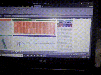
Step 5: Data Visualization
To visualize our information taken by the movement of our sensor, we decided to use the new Excel add-on created by Hacker STEM (a Microsoft group) called Streamer Data (Initially known as the Cordoba project).
Thanks to this tool we can connect our device with Microsoft Office Excel and see in real time the data taken by the sensor. Likewise we can record and take compilable evidence with it.
VERY IMPORTANT: This add-on only works on Windows 10 operating system (We had problems and can not run on a lower one). It is also important to have the Microsoft Office 2016 package (preferably 365). It does not work in previous versions of Office.
- Enter this
URL
Download the Visual Studio Tools tool because if you do not it will show error in the installation of Data Streamer.
- We execute the file that we have downloaded and follow the installation steps.
- After having completed the previous steps. We enter:
Microsoft Data Streamer
- Download and run the file with administrator permissions. After the installation, we can count on the tool in Excel.
- Download and open the file that has been designed for the data of this prototype (You can download
https://drive.google.com/file/d/1PYVryrcP-97At12KqXsPd5LuAtafr9TJ/view?usp=sharing
)
- We go to Data Streamer in Excel.
- We click on the Connect a device option. We select our device.
- When you are ready click on Start and start monitoring and taking data. You can visualize how the graphics and sketches move with the movement of the structure where you have placed the prototype.
- If you want to record and save the information you have those options in Data Streamer.
Additional Information
Results
Following all the steps we have managed to design and build a monitoring system with AI that identifies and records structural movements generated either by action of nature (Earthquakes, earthquakes) or by human error (Engineering error and calculations) thanks to powerful 3D Magnetic 2GB TLE493D A2B6 sensor from Infineon.
Thanks to this monitoring system that collects data thanks to Infineon, it allows to have vital and precise information to know the structure status, to evaluate the conditions and weaknesses that the architecture and the current constructions present. We can also prevent possible collapses and landslides by identifying unusual movements.
We hope to integrate this system with emergency action sensors and the possibility of controlling emergency inputs and outputs, as well as sirens and alarms when it is necessary to evacuate people from the building.
Below you can see some of the buildings collapses. The Infineon sensor aims to use these errors and get smart buildings.
Today thanks to its precision hardware it is a fact to be able to contribute in this field of engineering.
Special Thanks
I want to thank the team of Infineon and Hackster for allowing us to propose ideas and proposals that allow in a certain way to contribute to the development of our communities.
Today I propose a proposal for Smart Building that would not have been possible without the support of these two large organizations.
Thank you very much.
2018//08//25//02:31//IMPORTANT: AS WE KNOW THAT WE CAN NOT EDIT THE PROJECT DURING THE DESIGN OF THE JURY, WE WANT TO SAY THAT YOU ARE ATTENDED, JUST FINISH THE CONTEST WE WILL ADD A NEW CHARACTERISTIC TO THIS MONITORING SYSTEM.
WE ARE WORKING TO TAKE WEIGHT CONTROL DATA THAT IS EXERCISED ABOVE THE COLUMNS ALLOWING WARNING OF POSSIBLE STRUCTURAL WEAKENING OR OVERWEIGHT COLLAPSE. ALSO WE WERE INCLUDING A SENSOR OF TEMPERATURE AND HUMIDITY TO INCORPORATE IT TO THE COLUMNS OF THIS MODE EVALUATE POSSIBLE COLLAPSE BY FILTRATION OF LIQUIDS BETWEEN THE COLUMNS AND SUPPORTS OF THE BUILDINGS.
MANY THANKS FOR NEW INFINEON AND HACKSTER, I HOPE TO MAKE MANY IDEAS MORE WITH YOUR MAGNETIC SENSOR!
Comments are not currently available for this post.