Categories: Beginner
Hello,
Okay so, I started reading another book again, "Exploring BeagleBone, " and came across Chapter 6 with a LDR or photoresistor example with the sysfs entry example.
Nice.
Also, Dr. Molloy produced a C++ script for testing the sysfs entry via software.
…
Okay now, we need some ideas on Photoresistors and a clue on how to wire this bad pup up. So, bear w/ me and I will discuss a bit about LDR (light dependent resistors) or what we call Photoresistors.
…
From general knowledge, the LDR sensor acts on light. If it is dark in your room or if you have a flashlight high against the sensor, you will see different analog to digital conversions in a sysfs entry on your BBBW (beaglebone black wireless). Also, the Photoresistor has many ideal applications in case you are an avid analog user.
…
So, the photoresistor in a higher resistance state is in that state because of a lower light "situation." This situation can b/c of the darkness in Alaska or because your bedroom light is off. The lower resistance in the light sensor is from higher amounts of light. So, if you are in the Sun or just handing out candy at your home during the night, the LDR will have a different reading in the sysfs entry portion which is located on your BBBW at:
/sys/bus/iio/devices\iio:device0
That sysfs entry is for the ADC on the BBBW. ADC or analog to digital converter is a chip that turns analog signals into digital numerical values based on the voltage.
So, say we have a photoresistor and we have this light dependent resistor near the flashlight head w/ the flashlight beam directed at the LDR, we then would see a lower resistance in our sysfs entry which would be a higher digital number if we were to use this command in the terminal:
cat in_voltage0_raw
The cat command brings up a visual concatenated numerical value which is basically just writing to our terminal the sysfs entry of our LDR which is directed to digital values from analog signals.
There is a million different way to state what I just tried, and tried I did, to explain.
…
Please go easy on me. Okay so, now we have a little knowledge or background info. on using the device of choice in the tutorial from that specific book I mentioned earlier.
…
Play around w/ it. Use a flashlight! Bring out your wiring into the Sun and try to run the cat command mentioned on your BBBW.
Or…
Go into a pitch dark room, like a closet, and run the command while you are plugged in via your computer. Just remember to cover the computer screen. Light!
…
Oh and this is putting it ever so eloquently:
A photoresistor is a type of resistor that reacts to light. Also known as a light-dependent resistor, a photoresistor can be used to indicate the presence or absence of light and change the way a circuit behaves accordingly. Resistance through photoresistors is higher in low levels of light and lower in high levels of light.
How do photoresistors work?
This change in resistance occurs due to the material the photoresistor is made of. Electrical currents are created when electrons move within a material. As such, materials that have a high number of free electrons that can easily move around are considered good conductors. For photoresistors, materials with high resistance, aka a low level of free electrons, are used. With this high-resistance material, most electrons are locked into place. However, as light falls on the photoresistor, the light photons are absorbed, and their energy is transferred to the electrons, allowing some of them to break free and move about. This change lowers the resistance of the photoresistor and allows electricity to move more freely through it.
This "How do photoresistors work?" couple of paragraphs were mentioned on a website called Sparkfun which can be found here:
http://blog.sparkfuneducation.com/what-is-a-photoresistor.
…
My rendition is not as well founded in facts but you make your choice.
Okay so, now that we have gone over a location on the Linux file structure called the sysfs section, we can use it to our advantage on the BBBW b/c of the ADC and the header pins.
There are seven analog inputs on the BBB and BBBW. You can search here for available pins and configurations that can be used:
https://beagleboard.org/Support/bone101
Just scroll down the page and you will find the pins available that you can use.
…
Seth
P.S. I will list some software from Dr. Molloy in case you are tired of hitting your up arrow to rerun the sysfs entry command on your terminal. If you get bored, please add your comments or suggestions. I will make this nightlight soon in Python3 so we can all use it:
https://learn.sparkfun.com/tutorials/sparkfun-inventors-kit-experiment-guide—v40/circuit-1c-photoresistor?__hstc=250566617.4b84405c2b2192afa1e19f8d75ae7c98.1573348212675.1573348212675.1573348212675.1&__hssc=250566617.1.1573348212675&__hsfp=765294456&hsCtaTracking=ef752c94-3bc4-40be-bd84-38385170c70e%7C38332e58-8350-4164-a615-4897be22f38a
Before I forget:
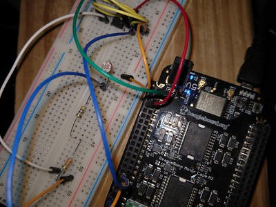
Here is the photo of the schematic w/ wires, the LM358PE4 Op Amp and resistors:
And…
Oh and here is the location for your Op Amp, i.e. the LM358PE4 from Texas Instruments:
https://www.mouser.com/ProductDetail/595-LM358P.
You can find your datasheet on that page if you scroll down.
…
Oh and if you try out that python3 source, keep your Op Amp wired up like the above photo. It will work. I have not attempted it yet w/ the LED. So, so far, the idea is that it will print to terminal like so:
You can see when I held light to the LDR on the seventh line.
Enjoy!
Comments are not currently available for this post.