Categories: Intermediate
UPDATE (19 July 2016):
This boat is going to compete in the World Robotic Sailing Championships in Portugal.
Read here for more information
.
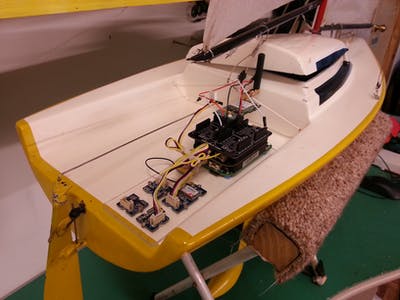
This article describes how to get the BeagleBone Green working as a remotely controlled device that can send back status updates (position and attitude) to the controller.
See the video below for the awesome demo. It shows the device connected to a sailboat, but you could connect it to anything.
It’s simple, there is almost no soldering required – only the GPRS modem pins require soldering. We only use JavaScript as our programming language. This means, as an Internet of Things developer, you only need to focus on one language.
The full system I describe requires the following components, but you can pick and choose the components you need for your own project:
- 3-Axis Compass (i2c)
- 3-Axis Gyroscope (i2c)
- 3-Axis Accelerometer (i2c)
- GPS receiver (serial)
- GPRS Modem (serial, 2G GSM) – for the Internet connection
- 2x servos (PWM)
I will describe how to get each component working individually, including the complete code to see in the video demo. All the code is open sourced so you can contribute back to it.
Note: it works for the BeagleBone Black too. Heck, a lot of these instructions will also work on the Raspberry Pi too, but your mileage may vary and I can’t support you for that.
Below is an example of the orientation (attitude) of the final device. It uses the
Madgwick algorithm
to smooth out the noise. Although I have written a
library
for this, I have not included it in the tutorial.
Overview
Below are the steps I will take you through.
- Why JavaScript?
– explain why JavaScript is so awesome.
- Prerequisites
– what you need to know before undertaking the tutorial.
- Compass
– how to get the compass working.
- Gyroscope
– how to get the gyroscope working.
- Accelerometer
– how to get the accelerometer working and it’s limitations.
- GPS Receiver
– this is a serial device, how to get this going.
- GPRS Modem
– how to get this going using pppd to connect us to the Internet.
- Servos
– how to control the servos.
- Power Source
– attaching a power source to make it truly remote.
- Remote Control
– in the last step we will communicate with it.
Why JavaScript?
For this project all the code has been written in JavaScript. The BeagleBone is nice because it allows you to run a full blown JavaScript (node.js) system. Since JavaScript is the language of the Internet it makes sense to use it in IoT (Internet of Things) devices. JavaScript is fast enough, great at creating network connected devices, it’s easy to learn and if your an Internet of Things developer, it likely that you already know it well.
node.js
is an extremely popular JavaScript engine that runs your JavaScript code on a server… or on the BeagleBone, it’s used extensively to build websites and other network back-end systems.
The BeagleBone Green comes with a library called
BoneScript
, this allows you write code in JavaScript and access the hardware on the BeagleBone. In this tutorial I will show you how to use JavaScript to interface with all the mentioned hardware. Note that I will use
OctalBoneScript
instead of BoneScript. OctalBoneScript is a fork that is actively maintained and has
been enhanced
to use some nice JavaScript features that BoneScript does not.
Prerequisites
This section describes what you need to know before you begin building. I have built my device onto of some perspex, you can do the same or use another method (e.g. 3d printer). I don’t go into the detail of the perspex sheet.
You will need be familiar with the following:
- The
BeagleBone Green
or
BeagleBone Black
: Essentially they are the same, with some minor
differences
. For this project I recommend the Green since the Green has Grove connectors which much things much tidier. Read up about the BeagleBone. The
forums
are a great place for support.
- Editor / IDE
: I recommend using Cloud9 IDE, it comes with the BeagleBone and is accessible from your browser. I tested this tutorial using Cloud9 IDE, but normally I develop on my desktop using
Atom Editor
(also based on JavaScript).
- Linux
: The BeagleBone series run Debian GNU/Linux. You will need basic command line fu, but I will try to avoid it whenever possible. Here is a basic
tutorial
. Note: from Cloud9 you can open the Linux terminal (command line) by pressing the [ALT]+[T] keys together.
- Linux Editor
: Cloud9 is great for coding, but it does not allow you to edit system files (probably a good thing). So you should become familiar with a text editor, I suggest
nano
, it does not have a steep learning curve. Although I typically use mcedit or vim.
You will need the following tools:
- Drill for drilling the screw holes in the perspex (not described). I use small Torx screws which were scavenged from hold computer hardware.
- Tape / glue – for fixing the GPS antenna.
- Screw driver.
- Saw and file cutting and finishing the perspex.
- 4GB micro SD card for loading the new version of Debian.
- Activated SIM card for the GPRS Modem. SIM card size is standard sized.
- Power source for wireless operation – I use a USB power bank.
Upgrade to Debian 8.1+
The BeagleBone Green currently comes with Debian 7.8 by default. However, these instructions require Debian 8.1 or above, I tested them on Debian 8.3. The reason is that Debian 8.3 has Linux kernel 4.1.x, which has more stable cape manager for the BeagleBone. Octalbonescript will also only work with this version, or above.
Download the latest Debian image from
https://beagleboard.org/latest-images
. Install this on the 4GB micro SD card (instructions are
here
). All you need to do is insert the SD card into the BeagleBone Green and it will boot with Debian 8.3. All changes you make will be saved to the SD card.
Once you have booted the BeagleBone, you should update the software and operating system. Use Cloud9 IDE on your BeagleBone (
http://192.168.7.2:3000
if you have your USB connected), ssh or
PuTTY
(in Windows) to access the BeagleBone.
In Cloud9 IDE press [ALT]+[T] to get the Linux command line. Then type:
apt-get update
The above command downloads all the updates from the Debian repositories. And the following command will action the updates (this can take 10 minutes or longer):
apt-get -y dist-upgrade && apt-get autoremove
After upgrading you should also reboot. You can press the RESET button the BeagleBone Green.
Device Tree Overlays (DTO):
We need to make sure the correct device tree overlays (capes) load at boot time. In a nutshell a DTO describes to the ARM processor which pins are where and activates then given pins (since one GPIO pin can have multiple functions). Below are a couple of links describing DTOs in more detail:
I find the following diagram helpful too:
To manage the boot-time loading of capes/DTOs, we need to edit the
/boot/uEnv.txt
file. Using
nano
to make the edit, on the command line type:
nano /boot/uEnv.txt
and change the following line:
cmdline=coherent_pool=1M quiet cape_universal=enable
to:
cmdline=coherent_pool=1M quiet
and add the following new line to the file:
cape_enable=bone_capemgr.enable_partno=cape-universaln,BB-ADC
then save the file and reboot. What this does is load the capes we require for this project.
Planning the Physical Layout
Some things to keep in mind for the layout.
Aligning x, y, and z coordinates of devices
The accelerometer, compass and gyroscope all have an X-Y-Z graphic printed on the circuit board, see picture. You should align these together such that the board for each is in the same direction.
Accelerometer and gyro physically close
The accelerometer and gyroscope integrated circuits should be physically close to each other, this ensures when we put all the data together we take the information from one point.
Plan Your Board Layout
It’s best to plan a bit first, I suggest for each component, decide which pin it is going to occupy. I put this into a spreadsheet. Below is my plan along with the BeagleBone pins.
Accelerometer
The
Grove 3-Axis Digital Accelerometer(±1.5g)
has 3 orthogonal accelerometers. An accelerometer can measure gravity as well as acceleration/movement in a direction. Accelerometers are generally very noisy devices, I have seen this accelerometer fluctuate ±5 degrees when lying still. They also have a low resolution, meaning that smallest angle of resolution is 2.7 degrees from vertical. However, this is a know issue with accelerometers in general and when you pair them with a compass and gyroscope as well has use noise filtering you can reduce this issue.
This accelerometer measure a g-force up-to 1.5g, which is good for general use and swaying, but not good if you want accurate tap or knock detection. For that you need a larger range accelerometer,
like this one
.
First connect your accelerometer to your BeagleBone Green, see photo below. The BeagleBone i2c Grove connector is connected to the i2c-2 bus.
Communication is over the i2c bus, the Grove connectors make it seamless to connect to the BeagleBone Green. This accelerometer contains a
Freescale Semiconductor MMA7660FC
chip.
I wrote the
accelerometer-mma7660fc
library which is available on npmjs.org and GitHub. First we need to install the library, on the command line:
npm install accelerometer-mma7660fc
This will take a minute to download and install the accelerometer-mma7660fc library. It will create the node_modules folder (if not already there) and place the new library into that folder.
Create the following file named
gyro-test.js
:
var MMA7660FC = require('accelerometer-mma7660fc');


// The initialiser is the i2c bus number that the accelerometer is on.

var accelerometer = new MMA7660FC(2);


// How often to poll the accelerometer (in milliseconds)

var INTERVAL = 100;


// setInterval will run a function every 100 ms to get values from the

// accelerometer.

setInterval(accelGetValues, INTERVAL);


// Get the accelerometer values - the values object will be returned

// with x, y, z values which represent the G Force in the respective

// direction.

function accelGetValues() {


   accelerometer.getValues(function (err, values) {

       if (err) {

           console.error(err);

           return;

       }

       // Print out the x, y, z values which we received.

       console.log(values);

   });

}
In Cloud9 click run (see green play icon) or use [ALT]+[F5]. This will run the code, it may take a few seconds to start. You should see a similar output as the following.
debugger listening on port 15454

{ x: 0.094, y: 0, z: 0.984 }

{ x: 0.094, y: 0, z: 0.984 }

{ x: 0.047, y: 0.047, z: 1.031 }

{ x: 0.047, y: 0.047, z: 0.984 }

{ x: 0.094, y: 0.047, z: 0.984 }

{ x: 0, y: 0.047, z: 0.984 }

{ x: 0.047, y: 0.047, z: 0.984 }

{ x: 0, y: 0.047, z: 0.984 }
Compass
The
Grove 3-Axis Digital Compass
has 3 orthogonal magnetometers and can detect the Earth’s magnetic field. Communication with this device is over the i2c bus. This compass contains a
Honeywell HMC5883L
chip.
Let’s continue to build on top of the accelerometer and add the
Grove Cape for BeagleBone Series
and compass. You do not need the Grove Cape, but you can simply use the
Grove i2c hub
, it’s a simpler and more elegant solution.
Push in the Grove Cape, this can take some force – but don’t apply too much. Connect the compass to i2c-1 port of the Grove Cape. See photo below.
I created the
compass-hmc5883l
library, is available on npmjs.org and GitHub. First we need to install the library, in the command line type:
npm install compass-hmc5883l
This will take a minute to download and install the compass-hmc5883l library.
Create the following file named
compass-test.js
:
// This will load the compass library.

var HMC5883L = require('compass-hmc5883l');

var compass;


// How often to poll the compass (in milliseconds)

var INTERVAL = 100;


// This is required to initialise i2c-1 - currently used for the compass.

var obs = require('octalbonescript');

obs.i2c.open('/dev/i2c-1', 0x1e, function(data) {

       console.log('data:', data);

   }, function(error, wire) {

       if (error) {

           console.error('Error opening i2c device: ', error.message);

           return;

       }

       // The i2c bus has been initialised once we get here.

       console.log('Loaded i2c-1.');


       // Connect with the HMC5883L compass on i2c bus number 1

       compass = new HMC5883L(1);

       // setInterval will run a function every 100 ms to get values from

       // the compass.

       setInterval(compassGetValues, INTERVAL);


   }

);


function compassGetValues() {


   // Get the compass values between x and y.

   compass.getHeadingDegrees('x', 'y', function (err, heading) {

       if (err) {

           console.error('There was an error from the module: ', err);

           return;

       }

       console.log('Heading:', heading);

   });

   // Get the raw values

   compass.getRawValues(function (err, values) {

       if (err) {

           console.error('There was an error from the module: ', err);

           return;

       }

       console.log('Raw x,y,z values: ', values);

   });


}
Run your code, you should see a similar output as the following. The values should change as you rotate the compass around the z-axis.
debugger listening on port 15454

Loaded i2c-1.

Heading: 40.50894130751047

Raw x,y,z values:  { x: 49, y: 310, z: 342 }

Heading: 40.70309146835619

Raw x,y,z values:  { x: 47, y: 311, z: 341 }

Heading: 40.31395364571046

Raw x,y,z values:  { x: 51, y: 309, z: 343 }

Heading: 40.43330827236527

Raw x,y,z values:  { x: 50, y: 311, z: 343 }
Gyroscope
Next up we add the
Grove 3-Axis Digital Gyroscope
, it has 3 orthogonal gyroscopes. A gyroscope (gyro) measures rotational acceleration. So when the device is at rest, all gyros will report values around zero. This SparkFun gyro contains a
InvenSense ITG-3200
chip. Again, like the accelerometer gyros are generally noisy, so you will see the values fluctuate.
Connect the gyro to i2c-2 port of the Grove Cape. See photo below.
Install the
gyroscope-itg3200
library, type the following on the command line:
npm install gyroscope-itg3200
Create the following file named
gyro-test.js
:
// This will load the gyroscope library.

var Gyroscope = require('gyroscope-itg3200');


// How often to poll the gyroscope (in milliseconds)

var INTERVAL = 100;


// The initialiser is the i2c bus number that the gyroscope is on.  We can also

// set the sample rate.

var gyro = new Gyroscope(2, { sampleRate: INTERVAL });


// The gyro needs calibration first.  During calibration it needs to be at rest.

gyro.calibrate(function () {

   // Get the accelerometer values every 100 milliseconds

   setInterval(gyroGetValues, INTERVAL);

});


// Get the gyroscope values - the values object will be returned

// with x, y, z values which represent the angular acceleration

// around the respective axis.

function gyroGetValues() {

   gyro.getValues(function (err, values) {

       if (err) {

           console.log(err);

           return;

       }

       console.log(values);

   });

}
The output should look like something below. You also notice the "temp" value which is the temperature in degrees, however it is currently returning incorrect values due to a bug in the code – which has since been fixed.
{ temp: -2.8535714285714286,

 x: 0.09739130434782606,

 y: -0.1530434782608695,

 z: 0.02782608695652178 }

{ temp: -2.7964285714285713,

 x: 0.09739130434782606,

 y: 0.19478260869565212,

 z: -0.0417391304347825 }

{ temp: -2.9107142857142856,

 x: -0.25043478260869567,

 y: -0.08347826086956522,

 z: -0.11130434782608689 }
GPS
Next up:
Grove GPS
. A simple GPS receiver with an aerial. I have found this device to be reliable (compared to another brand I tried) and reasonably quick at picking up GPS signals.
Connect the GPS to UART1 (J2) on the Grove Cape, see the photo below. To secure the aerial I just used tape (unlike in photo). You should see a the green PWR light come on. On BeagleBone Linux UART1 relates to the device driver
/dev/ttyO1
.
Unlike the previous devices, this one does not use i2c, it uses the serial bus (UART). Since most GPS devices communicate over serial and speak NMEA (a GPS protocol), most GPS devices can use the same driver. However, I found the packages on npm did not suit my requirements so I created my own, it’s called
super-duper-serial-gps-system
.
Let’s get it running with node, so to install:
npm install super-duper-serial-gps-system
Create a file named
gps-test.js
:
var SERIAL_PORT = '/dev/ttyO1';


// We require octalbonescript just to initialise the serial port.

// This only needs to be done once, every time we boot.

var obs = require('octalbonescript');


// Load the GPS module

var SerialGPS = require('super-duper-serial-gps-system');


// Enable serial for such that we can use it for the GPS device

obs.serial.enable(SERIAL_PORT, function(err) {

   if (err) {

       console.error(err);

       return;

   }

   console.log('enabled serial: ' + SERIAL_PORT);

});


// This configures the serial port (to 9600 baud) and starts listening

// to the GPS device.

var gps = new SerialGPS(SERIAL_PORT, 9600);


// Monitor for 'position' event.  The data object is described below.

gps.on('position', function(data) {

   if (typeof data === 'undefined') {

       console.log('No GPS signal.');

   } else {

       console.log(data);

   }

});
The output may look like this if you are indoors or not in direct line of sight with GPS satellites:
debugger listening on port 15454

enabled serial: /dev/ttyO1

No GPS signal.

No GPS signal.

No GPS signal.

No GPS signal.

No GPS signal.
Outdoors you should get a GPS satellite fix, it can take a few minutes if you are surrounded by buildings. Once you get a fix, you will get the following output:
{ latitude: -36.85989,

 longitude: 174.75532333333334,

 alt: 123.6,

 altUnit: 'M',

 numSat: 7,

 horDilution: 1.52,

 timestamp: '232242.000',

 fixType: 'fix' }

{ latitude: -36.85989,

 longitude: 174.75532333333334,

 alt: 123.6,

 altUnit: 'M',

 numSat: 7,

 horDilution: 1.2,

 timestamp: '232243.000',

 fixType: 'delta' }
Wireless Internet: GPRS Modem
Next we connect the GPRS Modem, this allows you to use your local GSM (2G) cellular network to connect to the Internet, once you are wirelessly connected to the Internet anything is possible! You could also connect to the Internet using a
USB WiFi dongle
, but these use more power than and will drain your battery if you are going to be truly wireless.
This section is lengthy, we will follow these steps:
- GPRS Step 1: Connect the hardware.
- GPRS Step 2: Configure the GPRS module for faster Internet.
- GPRS Step 3: Configure the Internet connection using pppd.
- GPRS Step 4: Connect to the Internet.
So I am using the
GSM2 Click
with a GSM antenna (MIKROE-275) on top of the
MikroBus Cape
. This device has the
Quectel M95 FA GSM/GPRS module
. Before you purchase it, make sure your cellular network provider supports the listed 2G frequencies. This device uses the serial port for communications, we will use UART2.
GPRS Step 1: Connect the hardware
The GSM2 Click comes with the pins unsoldered, you need solder these on – see section 2 of the GSM2 Click user manual for instructions. Insert the activated SIM card (standard size) into the SIM card slot and lock the slot. Attach the GSM aerial. Insert the GPRS modem onto slot 1 of the MikroBus Cape. And finally push the MikroBus Cape firmly on top of the Grove Cape. When powered on, you should see the yellow STAT light on and the red NET light flash.
GPRS Step 2: Configure the GPRS module for faster Internet
The Quectel M95 module has a lot of features. One of the features is that the M95 module should automatically detect the communication speed (baud rate – you can think of it as bits per second or bps) of the serial line. However, I found this is not the case – at least not for me. So we need manually set this and save it to the firmware. By default it behaves well at 9600 baud, but if you want faster Internet speeds then you will need to increase this value. The maximum speed is 115200 BAUD.
If 9600 baud is good enough for you, then you can skip this section
.
We need to install
minicom
to manually communicate over the serial line, configure the M95 and save the settings such that they are not lost on boot.
But first, we need to enable the UART2 serial port (
/dev/ttyO2
). Create and run the following JavaScript code – you should get "
enabled serial: /dev/ttyO2
":
// Set out serial port

var SERIAL_PORT = '/dev/ttyO2';


// We require octalbonescript just to initialise the serial port.

// This only needs to be done once, every time we boot.

var obs = require('octalbonescript');


// Enable serial for such that we can use it for the GPS device

obs.serial.enable(SERIAL_PORT, function(err) {

   if (err) {

       console.error(err);

       return;

   }

   console.log('enabled serial: ' + SERIAL_PORT);

});
Then on the command line enter the following – this installs minicom:
apt-get install -y minicom
Once minicom is installed enter the following – this will start minicom at 9600 baud and connect us to UART2:
minicom -b 9600 -D /dev/ttyO2
You should see something like the following:
Now in the console type
AT
and hit the enter key. You should get an
OK
as the response, see image below. Congratulations! You are talking to the M95 GPRS modem.
All modems have a series of AT commands, these AT commands tell the modem what to do, they typically give you a response. The M95 AT commands are well documented on the Quectel M95 product page, under downloads see the "Quectel_M95_AT_Commands_Manual_V3.2.pdf" document, a login is required but registration is free.
Next I will show you how to set the baud rate of the device to 115200 (the maximum possible speed), however, you can set it to what ever valid value that suits you. First we need to detect the baud rate, so in minicom type the following command:
AT+IPR?
This should give you a response of:
0
To list the set of valid baud rates type:
AT+IPR=?
Now you can set the value:
AT+IPR=115200
and the response is probably not shown or garbled. This because the speed of the UART2 communication has changed and minicom is still expecting 9600 baud.
To exit minicom:
type [CTRL]+[A], [Z], [X].
Next we start minicom again at 115200 baud
minicom -b 115200 -D /dev/ttyO2
and check all is working again by typing in
AT
, you should get
OK
as a response.
There are numerous other AT commands, these allow you to interact with the modem and determine things like the cellular signal strength, send/receive SMS, handle voice calls, etc. I won’t discuss these here.
GPRS Step 3: Configure the Internet connection using pppd
To make our device really awesome, it needs to connect to the Internet remotely. We have the hardware and configured the modem, but now we need the software to drive the modem and make an Internet connection. We will use the
Point-To-Point Protocol (ppp)
to make a connection to Internet, we will install
pppd
, configure it and run it. pppd is highly configurable and will handle cellular network authentication, re-connection in case of a lost connection, etc.
To install pppd type the following in the Linux console (it may already be installed):
apt-get install -y ppp
Replace the
/etc/chatscripts/pap
file contents with the following (type "
nano /etc/chatscripts/pap
" on the command line):
TIMEOUT      60

ABORT        BUSY

ABORT        VOICE

ABORT        "ERROR"

ABORT        "NO CARRIER"

ABORT        "NO DIALTONE"

ABORT        "NO DIAL TONE"

""            ATZ

OK           AT+CGDCONT=1,"IP","internet","0.0.0.0",0,0

OK           ATDT\T

CONNECT      ""
IMPORTANT
: the line with
AT+CGDCONT
contains the
APN (access point name)
(or "WAP connection string") which is specific for your cellular network provider. You may need to change the "internet" string.
Replace the
/etc/ppp/peers/provider
file contents with the following:
# MUST CHANGE: replace myusername@realm with the PPP login name given to

# your by your provider.

# There should be a matching entry with the password in /etc/ppp/pap-secrets

# and/or /etc/ppp/chap-secrets.

user ""

password ""


# MUST CHANGE: replace *99***1# with the phone number of your provider.

# The /etc/chatscripts/pap chat script may be modified to change the

# modem initialization string.

connect "/usr/sbin/chat -v -f /etc/chatscripts/pap -T *99***1#"


# Serial device to which the modem is connected.

/dev/ttyO2


# Speed of the serial line.  If you skipped "GPRS Step 2" then leave this at 9600.

115200


# Assumes that your IP address is allocated dynamically by the ISP.

noipdefault


# Try to get the name server addresses from the ISP.

usepeerdns


# Use this connection as the default route.

defaultroute


# Makes pppd "dial again" when the connection is lost.

persist


# Do not ask the remote to authenticate.  This works for my provider.

noauth


# 'noccp' disables CCP (Compression Control Protocol) negotiation.

# I had to use to successfully connect to my provider, you may wish to

# disable.

noccp


# 'novj' disables Van Jacobson style TCP/IP header compression in both

# the transmit and the receive direction. I had to use to successfully

# connect to my provider, you may wish to disable.

novj


# I have included debug to debug issues.  The debug messages are written

# to /var/log/message.

debug
Note:
The above file is my actual provider file. Your provider may require different values, read the comments for an explanation.
GPRS Step 4: Connect to the Internet
We are almost wirelessly connected to the Internet! Connecting with pppd is really simple, on the command line you type:
pon
and to disconnect:
poff
While connected try pinging google with the follow command:
ping google.com
Debugging the GPRS connection:
However,
pon
and
poff
aren’t very verbose. Before you type
pon
you can type (in another command line window):
tail -f /var/log/messages
This will show you detailed connection information, you should see an output something like the following:
Mar 28 21:00:38 beaglebone pppd[879]: pppd 2.4.6 started by root, uid 0

Mar 28 21:00:39 beaglebone chat[882]: timeout set to 60 seconds

Mar 28 21:00:39 beaglebone chat[882]: abort on (BUSY)

Mar 28 21:00:39 beaglebone chat[882]: abort on (VOICE)

Mar 28 21:00:39 beaglebone chat[882]: abort on (ERROR)

Mar 28 21:00:39 beaglebone chat[882]: abort on (NO CARRIER)

Mar 28 21:00:39 beaglebone chat[882]: abort on (NO DIALTONE)

Mar 28 21:00:39 beaglebone chat[882]: abort on (NO DIAL TONE)

Mar 28 21:00:39 beaglebone chat[882]: send (ATZ^M)

Mar 28 21:00:39 beaglebone chat[882]: expect (OK)

Mar 28 21:00:39 beaglebone chat[882]: ATZ^M^M

Mar 28 21:00:39 beaglebone chat[882]: OK

Mar 28 21:00:39 beaglebone chat[882]:  -- got it

Mar 28 21:00:39 beaglebone chat[882]: send (AT+CGDCONT=1,"IP","internet","0.0.0.0",0,0^M)

Mar 28 21:00:39 beaglebone chat[882]: expect (OK)

Mar 28 21:00:39 beaglebone chat[882]: ^M

Mar 28 21:00:39 beaglebone chat[882]: AT+CGDCONT=1,"IP","internet","0.0.0.0",0,0^M^M

Mar 28 21:00:39 beaglebone chat[882]: OK

Mar 28 21:00:39 beaglebone chat[882]:  -- got it

Mar 28 21:00:39 beaglebone chat[882]: send (ATDT*99***1#^M)

Mar 28 21:00:39 beaglebone chat[882]: expect (CONNECT)

Mar 28 21:00:39 beaglebone chat[882]: ^M

Mar 28 21:00:39 beaglebone chat[882]: ATDT*99***1#^M^M

Mar 28 21:00:39 beaglebone chat[882]: CONNECT

Mar 28 21:00:39 beaglebone chat[882]:  -- got it

Mar 28 21:00:39 beaglebone chat[882]: send (^M)

Mar 28 21:00:40 beaglebone pppd[879]: Serial connection established.

Mar 28 21:00:40 beaglebone pppd[879]: Using interface ppp0

Mar 28 21:00:40 beaglebone pppd[879]: Connect: ppp0 <--> /dev/ttyO2

Mar 28 21:00:41 beaglebone pppd[879]: PAP authentication succeeded

Mar 28 21:00:41 beaglebone pppd[879]: local  IP address 100.100.100.100

Mar 28 21:00:41 beaglebone pppd[879]: remote IP address 192.168.254.254

Mar 28 21:00:41 beaglebone pppd[879]: primary   DNS address 118.148.1.10

Mar 28 21:00:41 beaglebone pppd[879]: secondary DNS address 118.149.1.10
Note: The
/var/log/messages
file is a log for all system activity, so you may see additional logs not related to pppd or chat.
Once connected you should also see a virtual network device created. Type ifconfig and you should see a section like the following:
ppp0     Link encap:Point-Point Protocol

        inet addr:10.144.153.104  P-t-P:10.144.153.51 Mask:255.255.255.0

        UP POINTOPOINT RUNNING  MTU:552  Metric:1

        RX packets:0 errors:0 dropped:0 overruns:0

        TX packets:0 errors:0 dropped:0 overruns:0
The Modem has a NET light. You can see the status of the connection with based on it’s flashing rate. There are 4 cases:
- Off: The module is not running.
- Flash every 800ms: Not connected with network.
- Flash every 2000ms: Connecting to the network.
- Flash every 600ms: Connected to network.
Servos
In this section I will describe how to connect one servo and get it running. Getting more servos running is just as simple, you just need spare PWM GPIOs.
Servos use
Pulse Width Module (PWM)
to determine the angle at which it should be set to. Again we use octalbonescript to set the servo angles. I use a
Futaba S3003
analogue servo. It can use 3.3V or 5V as the driving voltage, this can be driven by an external battery. The control line (white) is connected a BeagleBone PWM GPIO. I use P9_16 for one servo and P8_19 for the other (later in the documentation).
Servo 1:
- PWM (P9_16): White servo wire
- +3.3V (P9_03): Red servo wire
- Ground (P9_01): Black servo cable
Servo 2 (not used in this section of documentation):
- PWM (P8_19): White servo wire
- +3.3V (P9_03): Red servo wire
- Ground (P9_01): Black servo cable
Create a file named
gps-servo.js
:
// Note this code is adapted for octalbonescript from:

// http://beagleboard.org/support/BoneScript/ServoMotor/


var b = require('octalbonescript');

var SERVO = 'P9_16';

var duty_min = 0.03;

var position = 0;

var increment = 0.02;


// Initialise the PWM

b.pinMode(SERVO, b.OUTPUT, function (err, result) {

	console.log(err, result);

});


// Start our updates - this begin the continuous movement of the servo.

updateDuty();


function updateDuty() {

   // compute and adjust duty_cycle based on desired position in range 0..1

   var duty_cycle = (position*0.115) + duty_min;

   b.analogWrite(SERVO, duty_cycle, 60, scheduleNextUpdate);

   console.log('Duty Cycle: ', parseFloat(duty_cycle*100).toFixed(1) + ' %');

}


function scheduleNextUpdate() {

   // adjust position by increment and reverse if it exceeds range of 0..1

   position = position + increment;

   if(position < 0) {

       position = 0;

       increment = -increment;

   } else if(position > 1) {

       position = 1;

       increment = -increment;

   }


   // call updateDuty after 200ms

   setTimeout(updateDuty, 50);

}
Below is a video showing the connected servo in action.
Power Source
The final part to make your device truly wireless is a power source. The BeagleBone Green has 5V battery terminal pins (TP5-TP8) and there are a few places which document how to use these (
Element14
,
RaspBX
). There is also a
battery cape
.
But, I used the simplest option and that was to use a USB power bank (portable USB charger). This allows you to directly power the BeagleBone through the micro USB port.
This works for this project. However, if you are using different components or your servos are using a lot of power you may want to look at the alternate options. This would be using a 5V power source attached to the battery pins (TP5-TP8) and/or powering your servos from a different source.
Remote Control
In the steps above we have built all the necessary hardware and connected to the Internet. In this step we will set-up a solution to remotely control the servos and allow the device to send us status updates. This is the last step necessary to have a fully functional device. First I will explain the technology required to do this, then I will explain how to implement it.
Overview of the Solution
The diagram below shows the overview of the solution for the remote control and status updates. The components are:
- Controller
: This is a smart phone or tablet, when you tilt the
Controller
it will send commands to the the
Controlled Device
via the
Proxy
.
- Controlled Device
: This is our device we built, it connects to the
Proxy
and waits for commands from the
Controller
, while also sending status updates to the
Controller
.
- Proxy
: This forwards commands from the
Controller
to the
Controlled Device
, and vice-versa for status updates. The
Proxy
also creates a web-server that serves content, the
Controller
is just a simple web-page served by the
Proxy
.
Why can’t we communicate directly between Controller and Controlled Device?
We could if we were on the same internal network. But once you are remotely controlling devices over a GSM/Cellular network it is generally not possible to directly communicate with a device. For instance, you can’t directly access your phone’s IP address over the internet, there are a few reasons, one is security.
Setting up the Proxy and Controller
I have created an open source project,
web-remote-control
, that addresses this issue. It uses a lean communication protocol (based on UDP) to control the BeagleBone remotely.
First we will set up the Proxy server. If either the Controller or the Controlled Device is connecting over the cellular network then you need to setup a publicly accessible Proxy server (i.e. in the cloud), otherwise you can setup the server on your own PC, or even on the BeagleBone itself. For cloud servers I use
AWS
, but I recommend
Heroku
since it’s learning curve is less steep. Both come with free tiers so you should not have to pay for this. Note: you need to make sure UDP port 33330 and TCP ports 8888, 33330 and 33331 are open.
Once your cloud server is running and npm and node.js are installed, then run the following command on the server:
npm install web-remote-control
To start the proxy run the following command:
node runProxyAndWebServer
Your proxy and web-server is up!
The web-server serves the content for the Controller. We can access the controller using the following address:
http://[IP address of proxy server]:8888/
Where you need to enter the domain name or IP address of your server.
This link on your tablet or mobile phone is your controller.
Setting up the Controlled Device
Next we will set up the Controlled Device. We need to download
studious-octo-guide
, an open source project I created just for this tutorial. Then we go into the studious-octo-guide folder and install all the node.js dependencies. To do this, type the following commands on your BeagleBone Green:
git clone https://github.com/psiphi75/studious-octo-guide

cd studious-octo-guide

npm install
You can run this using:
WRC_URL=[IP address of proxy server] npm start &
You should see output like the following:
> studious-octo-guide@0.0.1 start /var/lib/cloud9/studious-octo-guide

> node the-whole-shebang/index.js


Starting the-whole-shebang

1459460817189 -0.1  -0.2  0.3   0.1   0     1    62.8  -292  201   342   null

1459460817245 0.1   -0.1  -0.1  0     0     1    72.7  -293  202   339   null

1459460817281 -0.1  0.2   -0.1  0     0     1    72.7  -293  202   339   null

1459460817317 -0.1  -0.1  -0.1  0     0     1    72.7  -293  202   339   null
Where the columns are:
- gyro: x, y, y
- accelerometer: x, y, z
- compass: heading, x, y, z
- gps: latitude, longitude (if receiving a signal)
Now you will be able to go to the controller and control your device.
Booting
We’re almost there! The last thing to do is to make sure that when we boot everything start, this means:
- enabling the serial port for the GPRS modem
- starting pppd using pon
- running the studious-octo-guide code
But first we install
forever
, this insures that in the unlikely event of that our code crashes it restarts:
npm install -g forever
We need to edit the
bbg-rc.localfile
in the
studious-octo-guide/the-whole-shebang/boot/
folder. Insert your Proxy IP details into the following line (remove the square brackets):
export WRC_URL=[IP address of proxy server]
We need to run the
bbg-rc.local
file at boot time. The
/etc/rc.local
file runs commands near the end of the Linux boot process. Use
nano /etc/rc.local
to edit the boot file, in this file we need to add the following line before the
exit 0
line:
/var/lib/cloud9/studious-octo-guide/the-whole-shebang/boot/bbg-rc.local
Reboot and your device should connect to the Proxy.
Our Superhero: The Sailboat
Great, if you’ve made it this far you have all the knowledge to put this together into one lean mean superhero. As in the demonstration video I have applied Remote Controlled BeagleBone device to a sail boat. But the other applications are endless.
I will be progressing the sailboat further. Follow the action on
anemoi.nz
. The idea is to create a fully autonomous sailboat, let me know if you are interested in contributing to the project which will be open source.
Let me know in the comments about your thoughts. If you have any questions I will be glad to answer them.
Comments are not currently available for this post.