Categories: Intermediate
Hello,
First off, sorry for the music. Secondly, yea boy!
I was first trying to get into motors by making them, of all things, just move.
Congratulations, I told myself in a quiet place. Outside of me being me, I advanced some knowledge through time to better incorporate my machines and actuators to live up to the glory of the name, i.e. motors!
…
With that typed out, let us just jump on in here. I got one or two DC-geared motors attached to the Sabertooth 2 x 12 and this specific motor driver is being powered by a 12v 1.3Ah battery (SLA). SLA stands for sealed lead acid. Nice acronym! They have many types of SLA batteries out in the world and they are all with different technologies.
Some are 12v 1.3Ah like mine that is going to be used in this short and others have different Ah, i.e. which stands for Amps an hour. So, my battery can provide 1.3 amperes an hour for my set up. Is it the best possible solution? That depends. Although, I am not the battery wizard some would like to thing of me as currently, I am studying a book I found recently on battery technologies, "The Tab Battery Book, (Root 2010)."
It is a good starter book for me on battery technology and other ideas associated with this realm of do-it-yourself ideas, mechanized mobility, and electromechanical instances (https://www.google.com/search?client=firefox-b-1-d&q=electromechanical).
So, we our one/two DC-geared motors, one/two stepper motors with four wires each for the stepper motors. Four wire, stepper motors usually indicate the A+, A-, B+, B- "standard"/Bipolar."
But, unlike some motors that come with documentation, there are actually cheaper, more readily available motors that have no such datasheets or documentation. B/c of this fact, a DMM (Digital Multimeter) is a very handy tool to test motors to figure out exactly where one stands on the contents of the motor interior. So, for instance, one might use the continuity test option on the DMM or a plain-ole continuity tester to figure out what exact two wires belong to the same "standard" or phase. For example, there may be four, different, labeled by color, wires each going into the motor. How are we supposed to know what exact two wires belong to the same phase? The wires are going into the housing and the housing is fastened together by machine screws (usually). So, without taking apart your newfound motor, this stepper motor, apply the continuity test to the wires to figure out the phase or better yet, put the DMM on the continuity test option, put your GND (Black) on one bare wire that is showing. Next, place the positive lead from your DMM on another wire? Do you hear the bzzt, bzzt noise from your DMM?
If not, try to move the positive lead from your DMM to another portion of a different bare wire. One should hear a slight ding from the DMM. If you have actually tested the four wires by the continuity test and have found that nothing is making sense, look here for a good debriefing from adafuit:
https://cdn-learn.adafruit.com/downloads/pdf/all-about-stepper-motors.pdf.
They have a nice short on Steppers and their aspects, interiors, and technology based around the entire phenom.
From what I have read, one would divide 360 (b/c of this being one full rotation) by the number of steps to find the degree of rotation. So, say we have a 400 step Stepper Motor in our hands and we need to figure out our degree of rotation, we could use this formula: 360 / 400 = __________ degrees?
I would use common core but I am an oldie but goodie. So, without further ado, the answer to our formula equation is "get a calculator" or if you are in a lower grade, learn by performing that equation from the formula.
360 degrees / 400 steps = 0.9 degrees per step
So, our 400 step Stepper Motor(s) would preferably move 0.9 degrees per step.
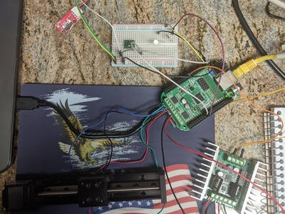
So, here is where you can see a simple set up of DC motor w/ the Sabertooth 2 x 12, a limit switch, a LED, and a stepper with a slide attached to the Motor Bridge Cape on our
Beagleboard.org
and
SeeedStudio.com
BeagleBone Green Gateway.
Anyway, here is a brief set up for making the motor move (DC and stepper).
Oh. I forgot. We need to get the source first. So, if you have your image set up on your board, we can proceed. If not, please view this link:
https://beagleboard.org/getting-started
That link will bring you to
beagleboard.org
and to the section of their site where you can learn how to put an image on their board(s). If you would, just use the SD Card version or if you do not have a SD Card, just use the flasher image for burning the Debian Distro onto the eMMC on the BeagleBone Green Gateway.
Now, we need to, luckily it is already installed with the current images, use git to clone a couple repos. on
github.com
and we also need to use pip3 to install a couple libraries from pypi.
https://pypi.org/
is the link to pypi. Python!
- with the newly installed image
- git clone
https://github.com/Seeed-Studio/MotorBridgeCapeforBBG_BBB - pip3 install pysabertooth
- I am pretty sure that Adafruit_BBIO is currently installed on the current image from beagleboard.org.
- pip3 install smbus2
- Now, if you want to use a virtual environment, please use this command to get the venv on your board for creating this virtual environment.
- sudo apt install python3-venv
- Now, from this command, mkdir NameADirectoryHere, cd into that directory.
- type this: python3 -m venv venv
- Now, cd into venv
- type: source bin/activate
- and repeat the installs while in a virtual environment so you can just use and follow the course of action on your packages
- So, pip3 install pysabertooth smbus2 flask adafruit-bbio
- Flask may be handy if you choose to start a simple server from your BBGG.
Now, we need to change the source in smbus2.py, MotorBridge.py, and type up a script to use for the Motor Bridge Cape, BBGG, Sabertooth, and our newfound love for motors!
Do you know how to find repos. or files in Linux or by using Python? It may come in handy while you are learning an environment or OS! Learn more, eat healthy!
Okay, outside of positive talk, let us now focus our attention to smbus2.py.
Once you have started your venv and are in the current working directory venv, please go to /lib/python3.7/site-packages/smbus2/ and type nano
smbus2.py
or use another text editor while on your system.
Change line 302 to look like this:
filepath = "/dev/i2c-2".format(bus)
Now, in our
MotorBridge.py
file, we need to change some source, too.
You can see some libraries that are no longer available or coined the term "deprecated" in source composition. So, we are going to use smbus2, pathlib, and Adafruit_BBIO.GPIO as GPIO.
This is the
MotorBridge.py
file first typed up by Jiankai Li in 2015. This is actually just the sections that have been changed by me and another person that found this repo. and provided support on Freenode, #beagle.
from smbus2 import SMBus

import time

import pathlib


# reset pin is P9.23, i.e. gpio1.17

reset_pin = pathlib.Path('/sys/class/gpio/gpio49/direction')

reset_pin.write_text('low')


bus = SMBus('/dev/i2c-2')


ReadMode    = 0

WriteMode   = 1

DeAddr      = 0X4B

ConfigValid =  0x3a6fb67c

DelayTime   = 0.005


...


def WriteByte(Reg, Value):

    data = [0 for i in range(2)]

    data[0] = Reg

    data[1] = Value

    bus.write_i2c_block_data(0x4b, 1, data)

def WriteHalfWord(Reg, Value):

    data = [0 for i in range(3)]

    data[0] = Reg

    data[1] = Value & 0xff

    data[2] = (Value>>8) & 0xff

    bus.write_i2c_block_data(0x4b, 1, data)

def WriteOneWord(Reg, Value):

    data = [0 for i in range(5)]

    data[0] = Reg

    data[1] = Value & 0xff

    data[2] = (Value>>8) & 0xff

    data[3] = (Value>>16) & 0xff

    data[4] = (Value>>24) & 0xff

    bus.write_i2c_block_data(0x4b, 1, data)

def SetDefault():

    WriteOneWord(CONFIG_VALID, 0x00000000)


class MotorBridgeCape:

    def __init__(self):

        reset_pin.write_text("high")

        time.sleep(1)
Now, those changes to the source are current as of 12/2020 with the current image of (uname -a) Linux beaglebone 4.19.94-ti-r57 and (cat /etc/dogtag)
BeagleBoard.org
Debian Buster IoT Image 2020-04-06. If something changes and you are attempting this effort for one or two steppers and one or two DC motors with a limit switch, please reply or respond.
Oh and here…without the board powered on, try these instructions. You do not want to have the BBGG powered when you are attempting to put wires into the pin headers. It may cause issues or harm the processor, the am335x.
The idea behind our changing of the source is so the libraries work with our current config. of the BBGG and Motor Bridge Cape along w/ the Sabertooth from Dimension Engineering.
So, plug in GND to GND from your limit switch to the BBGG. GND to GND (0v) from the Sabertooth to GND on the BBGG.
Use p9.21 as a TX UART from your BBGG w/ the Motor Bridge Cape attached to the S1 terminal on the Sabertooth. Do not add power just yet. We still need to configure the board to handle our set up and first the set up needs to be completed.
Now, b/c most limit switches are 5v, we will need to find one that is 3.3v so we do not harass our cpu into nonexistence.
Please be aware that the BBGG and other boards from
Beagleboard.org
only allow for 3.3v input and output technology logic outside of power and GND. So, for instance, if we were to use the PWM peripheral or a GPIO, 3.3v is our max input for these peripherals.
Plus, we can only source 4 to 6mA per pin. So, be careful while using specific sensors, tactile switches, and other push buttons.
A current limiting resistor is usually a good idea for reducing the current to the pin in case things decide to feed back through into the pin by "accident."
So, w/ our switch or w/ your switch, please use a resistor. If you know how much current/amperes the switch will put into the pin in question, a GPIO pin on p8.28 or p8.29 on the BBGG w/ the Motor Bridge Cape attached, use a formula to figure out exactly the type of resistor you will need to prevent damage to the BBGG or cpu SiP.
I used a 1000 ohm or 1k ohm resistor for my 3.3v switch. It is a limit switch. So, when it is hit, the motor performs an operation.
So, our limit switch needs to be powered to work as an input. So, we need to attach the power lead of the switch to p9.02 which is our 3.3v source.
The limit switch needs a signal or our digital GPIO signal, GND, and the 3.3v power pin.
That will cover our limit switch. Now, back to the entire set up.
Things are grounded and we can plug in the usb from our BBGG to the computer for development.
By now, some ideas have to be circulating. What about soldering the motor leads and attaching the quick disconnects to our leads?
Well, we need to do that too and if that has not been done yet, please turn your board off and fix this issue. Hand tools are needed in source programming. Now, we can see why. Jake, Brian, Susan, or Adam will not be there to do everything for you or for me. So, just like me and myself here, you will need to perform every action and then pick a favorite or stay general.
Yea!
Okay. Back to logic.
Given source is changed to suit our needs, we have a working image on our board in use, and wiring is fixed up so we can utilize source to alter the sensors and actuators. I know. This is taking forever.
Ha.
Here we go again. Plug in your board, attach two 12v 1.3Ah batteries to your two add-on boards.
1. Sabertooth
2. Motor Bridge Cape
Make sure your wiring is correct and your quick disconnects are ready to be pulled by positive first in case things go awkward or if there is a short you have not made into a circuit.
This is a starter script:
from pysabertooth import Sabertooth

from time import sleep

import Adafruit_BBIO.GPIO as GPIO

import MotorBridge


saber = Sabertooth('/dev/ttyS2', baudrate=9600, address=128, timeout=0.1)


LED  = "P8_28"

Stop = "P8_29"


GPIO.setup(LED, GPIO.OUT)

GPIO.setup(Stop, GPIO.IN)

motor  = MotorBridge.MotorBridgeCape()

MotorB = motor.StepperMotorBInit()


try:

    while True:

        if GPIO.input(LED):

            GPIO.wait_for_edge(Stop, GPIO.RISING)

            sleep(0.5)

            saber.drive(1, 25)

            sleep(5)

            saber.drive(1, -25)

            sleep(5)

            GPIO.output(LED, GPIO.LOW)

            sleep(2)

            GPIO.output(LED, GPIO.HIGH)

            sleep(4)

#saber.stop()

        elif GPIO.wait_for_edge(Stop, GPIO.FALLING):

            sleep(0.5)

            saber.drive(1, 50)

            sleep(5)

            saber.drive(1, -50)

            sleep(5)

        elif GPIO.wait_for_edge(Stop, GPIO.RISING):

            sleep(0.5)

            MotorB

            motor.StepperMotorBMove(0, 1000)

        else:

            MotorB

            motor.StepperMotorBMove(2000, 1000)

            sleep(2)

            motor.StepperMotorBMove(-2000, 1000)

            sleep(4)

except KeyboardInterrupt:

    print("Hey!")
This source shows:
- Importing libraries
- getting some communications set up under the heading saber
- Some pin declarations
- Setting up those pins under Adafruit_BBIO.GPIO rules and efforts
- Setting up Motor Bridge related instances
- Then, we have our try-except statement to cancel quickly w/out or w/ error to make sure we are in full control if no bugs are present.
- The while True statement runs continuously until we interrupt or until there is an action that halts our source, i.e. errors or bugs.
- Now…
Can anyone tell me what happens in the while True: statement?
Anyone?
Seth
P.S. Enjoy this starter script on the house for now. If you build something nice one day, I would like to see your work or made ideas relating to this post.
Comments are not currently available for this post.