Categories: Intermediate
Background
Melty Brain combat robots are rare types of full-body spinners in which the entire robot rotates about its center axis. The drive wheel(s) create the spinning motion, and the robot translates by turning the drive motors off for half of the rotation, creating a net velocity vector. While most combat robots have two separate systems – one for the drive train and one for the weapon system – a melty brain combines these into one system, eliminating the need for weight budgeting and ensuring that all of the robot’s mass goes into producing rotational kinetic energy. Thus, they can potentially be many times more powerful than other kinetic energy robots (shell spinners, bar spinners, etc.) in the same weight class. Like all kinetic energy weapon robots, melty brains seek to incapacitate their opponents by impacting them repeatedly at high velocity.
Project Overview
This melty brain circuit is designed to power a 3lb robot (AKA a "Beetleweight"). The robot receives three signals from the transmitter – forward/backward, left/right, and throttle. The processor onboard the PocketBeagle then computes the voltage to be sent to the motor over time. If the robot is instructed to simply increase its spin velocity, the motor will be fed a constant supply voltage. If it is directed to translate, the PocketBeagle instructs the motor to turn on and off at precise locations in its rotation cycle, producing a net velocity vector in the specified direction. For example, if a counterclockwise spinning robot is to move forward, the motor(s) will turn off for the half of the revolution in which they are momentarily traveling backward.
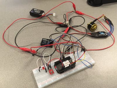
An accelerometer provides the necessary data to determine the exact time intervals required between on/off switches. An LED lights up whenever the robot is pointing in the desired direction, which allows the driver to know which direction the robot is facing. The whole system is powered by a 3S LiPo battery, and there is also a main power switch for safety. A 5V regulator ensures that the PocketBeagle and receiver each receive their recommended input voltages. The PocketBeagle controls each device with standard GPIO pins. The final version of the circuit will be constructed with standard 18-22AWG wire. However, for this prototype, it is sufficient to use a breadboard and accompanying jumper wires for signal connections and low voltages (5V or less).
Next Steps
- Update the wiring to reflect the final combat-ready version
- Build a test chassis
- Run tests with test chassis
Comments are not currently available for this post.