Categories: Beginner
Goal
Has the hot weather got you beat? Well, look no further because we’ve created the perfect solution for you – a mini AC unit which has a fan that turns on and off automatically based on the ambient temperature. With this project that you can replicate with a
PocketBeagle®
,
DC Motor Click
and
Weather Click
, you can make your very own unit to keep you cool in the heat! This step-by-step guide will make it easy – we promise that you won’t break a sweat (haha)!
The goal of this project is to show how easy it is to get up and running with the PocketBeagle®, which is an open-source Linux computer developed by BeagleBoard.org®. It features the
OSD3358-SM System in Package (SiP)
from Octavo Systems. The project also demonstrates how you can add new hardware to the PocketBeagle® without too much trouble.
Hardware and Software Basics:
BeagleBoard.org® PocketBeagle® Headers
The project will use the two headers of PocketBeagle® to connect to the MikroElectronika Click Boards. The following image shows the pin-out of these two headers.
The default function of each pin is highlighted in dashed line. Click Boards™ have a standardized
MikroBUS™
pin-out (shown below).
BeagleBoard.org® PocketBeagle®
(pictured below) headers conform to the MikroBUS™ standard and allow for two click boards™ to be interfaced with PocketBeagle® at a time (shown in the following figure). Although no guarantees are made with respect to compatibility, most click boards™ work with PocketBeagle® with a little bit of effort.
MikroElektronika produces hundreds of Click Boards that cover a wide range of capabilities and functions. We used
the Weather Click
which had already been used by the team in a project to make a
Health Monitor
with the PocketBeagle® to collect the temperature. In order to run the motor for the fan, we used the
DC Motor Click
, which has a DC motor driver on it. Since this was a
new Click for the PocketBeagle® community,
we needed to write new driver software for it.
Follow the steps below to make you very own mini AC unit.
Step 1: Install Click Boards on BeagleBoard.org® PocketBeagle®
Install the 2 Click boards into the 2 available positions on the PocketBeagle®. The positions are important as we need to select the device tree overlays according to them. For this project, we will install the DC Motor Click in position 1 and the Weather Click in position 2. By installing the Click boards in these positions, we select the interface with which the Click boards interact with the PocketBeagle®. The DC Motor Click and the Weather Click both use the I2C2 interface. The two Click boards installed on the PocketBeagle® are shown below:
Note that the microUSB port will be underneath the DC Motor Click.
Step 2: Download and Install the latest Linux image
Go to Beagleboard.org to download the latest Linux image:
https://beagleboard.org/latest-images.
Look for the Stretch IoT Debian Image for PocketBeagle® and click the link to download it (see below).
You should always start with flashing the latest image on your SD card. If it doesn’t work then you can try older versions.
Download and install an SD card programming utility onto your computer if you do not already have one. We recommend
https://etcher.io/.
Insert a new microSD card into a card reader/writer and attach it to your computer. Open the balenaEtcher application and follow the instructions for selecting the.img file and burning it from your computer to the microSD card(see below). This may take several minutes.
Eject the SD card when prompted and then remove the card. Insert it into the PocketBeagle® SD card slot – you should hear a satisfying click when it is completely inserted. Make sure that this happens before you power the system.
Step 3: Connect PocketBeagle® via Cloud9 IDE
Since you just downloaded the latest image, you should not need to install any USB drivers, but just in case, they can be found on the
BeagleBoard.org Getting Started Page
.
Use a microUSB to USB cable to connect PocketBeagle® to a computer/laptop. You should be able to bring up the Cloud9 IDE by entering the URL:
http://192.168.7.2:3000/ide.html
into the web browser. If you are using a mac, use
http://192.168.6.2:3000/ide.html.
You may also need to make sure that your computer’s network settings have been configured as such if you are using a mac:
Make sure you are using Chrome or Firefox. The IDE should look like the following figure:
Step 4: Connect PocketBeagle® to the Internet
In order to download the additional software packages required for this project, we first need to share our computer internet connection with the PocketBeagle®. Open up the control panel in Windows and navigate to the Network & Sharing Center (note that these steps will be different on MAC O/S and you should refer to BeagleBoard documentation for help with that):
Select the network connection where you connect to the Internet (in the case above, Wi-Fi). This window will pop up:
Select “Properties” and then click on the “Sharing” tab at the top of the new window that pops up:
Click to “Allow other network users to connect through this computer’s Internet connection, ” and select the connection (in the case above, Ethernet 6) to the PocketBeagle®. Click OK.
Now, you have to manually change the IP address and its settings on the PocketBeagle® network device. Click on the appropriate network (Ethernet 6 in the example) and go to Properties:
Click on “Internet Protocol Version 4 (TCP/IPv4)” from the list and then click Properties. In the pop-up window, add the IP address of the gateway (192.168.7.1) and the other settings shown below:
Click OK. At this point, you should have noticed that the connection has closed between the PocketBeagle®and your computer due to the network connection resetting. Just reload the Cloud9 page.
Now, we need to tell the PocketBeagle® how to connect to the internet connection via the computer gateway (IP 192.168.7.1). Since we will have to reboot the device multiple times during this process, we should save time by setting it up to connect automatically. First, type the following command into the Cloud9 terminal to test the USB connection:
ping 192.168.7.1
Ping is a debugging tool to test TCP/IP connections between devices. You should see an output on the screen, which is a response from your computer to say everything is ok. Press Ctrl+C to stop it.
Change to the “bin” directory below root and open a new script using the nano editor:
cd ~/bin

nano network.sh
Add the following lines to this file and press Ctrl+X to leave it. The editor will prompt you to save the changes you have made, so make sure to select Y for yes:
#!/bin/bash

/sbin/route add default gw 192.168.7.1

echo "nameserver 8.8.8.8" >> /etc/resolv.conf
This adds the computer gateway address to the PocketBeagle® IP address routing table and adds a name server to translate the IP addresses into names and vice versa. We also need to update the permissions so that this script is executable:
chmod 755 network.sh
Next, we will create a directory to store log files:
mkdirlogs
Now that we have this basic infrastructure, we can create our cron entry. First, we need to edit the"crontab" for root:
sudo crontab -e
(remember that the default password for PocketBeagle® is "temppwd").
This will prompt you to select an editor to add the cron entry; you can type 1 ENTER to open the nano editor. You should add the following line:
@reboot sleep 30 && sh/home/debian/bin/network.sh > /home/debian/bin/logs/cronlog 2>&1
This instructs cron that right after a reboot, it should first sleep for 30 seconds, and then execute our script. The output of the script and any error messages should be put into the file:"/bin/logs/cronlog". Now, reboot and check the connection:
sudo reboot

ping google.com
(Don’t forget Ctrl+C to stop the output.)
Step 5: Upload Code to Cloud9
First, transfer the attached file called dcmotordriver.py into the cloud9 directory of the PocketBeagle. You can do this by dragging the file and dropping it directly into cloud9 directory.
Next, transfer the attached zip file TempSensor.zip to PocketBeagle. Again, do this by dragging and dropping directly into the cloud9 directory.
You will need to unzip this file by using the command:
unzip TempSensor.zip
After this, we will make a log directory for these files. We will do so using the commands:
mkdir TempSensor/logs

mkdir dcmotordriver/logs
Step 6: Install Software
In order to run the code, there is some system software that we will need. We will be using some Adafruit libraries, but we need to make sure to update Adafruit_BBIO from 1.0.10 ti 1.1.1 to do this. Do so using the commands:
sudo apt-get update

sudo apt-get install build-essential python-dev python-pip -y

git clone git://github.com/adafruit/adafruit-beaglebone-io-python.git

cd adafruit-beaglebone-io-python

sudo python setup.py install
At the end of the process, you should see this:
Extracting Adafruit_BBIO-1.1.1-py2.7-linux-armv7l.egg to /usr/local/lib/python2.7/dist-packages

Removing Adafruit-BBIO 1.0.10 from easy-install.pth file

Adding Adafruit-BBIO 1.1.1 to easy-install.pth file

Installed /usr/local/lib/python2.7/dist-packages/Adafruit_BBIO-1.1.1-py2.7-linux-armv7l.egg

Processing dependencies for Adafruit-BBIO==1.1.1

Finished processing dependencies for Adafruit-BBIO==1.1.1
Now, we will install the necessary Adafruit code repositories in the /var/lib/cloud9 directory. (Note: the ‘run.sh’ script assumes that these commands are executed in the /var/lib/cloud9 directory):
Navigate to this directory if you aren’t already in it:
cd /var/lib/cloud9
And install the necessary Adafruit code repositories.
git clone https://github.com/adafruit/Adafruit_Python_PureIO

git clone https://github.com/adafruit/Adafruit_Python_GPIO

git clone https://github.com/adafruit/Adafruit_Python_BME280
Your Cloud9 screen should look like this after uploading the code and installing the necessary repositories:
The Weather Click Board uses a different I2C address setting than the default address in the Adafruit_Python_BME280 library. Therefore, we need to edit Adafruit_Python_BME280/Adafruit_BME280.py to change the I2C address of BME280 from 0x77 to 0x76:
nano Adafruit_Python_BME280/Adafruit_BME280.py


< ---- change line ---- >

# BME280 default address.

BME280_I2CADDR = 0x76
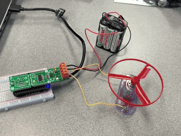
Step 7: Connect hardware
We wanted the DC Motor to be powered externally and not using the board itself, so we position the jumper J2 as shown in the picture below to make sure this was the case.
Now, connect your external power supply to the CN2 terminal on the Click Board. We used a generic battery pack which could fit 6 1.2 V batteries, so we supplied 7.2 V to the driver.
Finally, connect your fan to the CN1 terminal on the DC Motor Click.
Step 8: Run program!
Now it’s time to run the program. First, we need to make sure that our "run script", runmotor.sh, is executable. We will do so by making sure changing the run permissions. Make sure that you are in the TempSensor directory (which contains runmotor.sh) and then change the run permissions using the following commands.
cd TempSensor

chmod 755 runmotor.sh
Reboot:
sudo reboot
Now you can run the program! Navigate into the TempSensor directory, and run the program using the following command:
./runmotor.sh
The terminal should show you whether the fan should be on or off every time the temperature sensor takes a reading, which is every 5 seconds.
You just made your own fan! That was such a breeze (pun intended)!
Check out the video below to see the fan in action.
Conclusion
With some help from the BeagleBoard.org® community, adding a new Click board to the PocketBeagle is super quick and easy! While this project just controlled a fan, you can easily expand the OSD335x-SM to control entire HVAC and Building Automation and Control Systems. We hope that you enjoyed making this project, and that this project inspired you to make your own fun prototypes!
Comments are not currently available for this post.