Categories: Beginner
Hello,
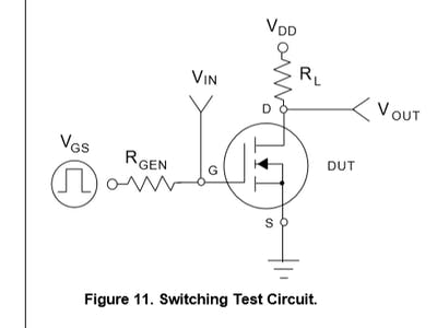
I am reading out of a book by Molloy, "Exploring BeagleBone." I came across a section on page 251 where there was a FET and a LED in a photo.
…
I wanted to try out how to make a disconnect and a connection via FET to an LED that is powered continuously. So, I embarked on and found an issue.
…
The entire set up works but it works without the FET, too. So, why use a FET?
- Faster switching speeds is one reason compared to a BJT.
- Another reason is that it switches quickly without delays.
These are two reasons on why FETs are used over BJTs. The FET used in this small article is a bs270. You can find the bs270 datasheet online by typing in "bs270 datasheet."
…
So, if I need a dense package and quicker times without delays, the FETs (Field Effect Transistors) would be a good choice.
Transistors of all kinds use different technologies. My pick for a FET, the N-Channel MOSFET which was one of the recommendations from the Molloy book listed earlier, uses electrons to block and basically switch on communication.
The FET in question can be used as a solid state switch that can "control" higher loads/currents than what the GPIO can provide. So, if you were to connect the FET source to GND and drain to vdd_5v, you would then use your gate, the middle pin on this N-Channel MOSFET to connect it to your GPIO.
…
On the BeagleBone Black, make sure your, either with the config-pin utility or by changing your directions w/ echo in the sysfs entries under GPIO, P9_12 pin is sourced to out and not as an input. We need that specific GPIO to be put as an output.
…
I came across some conflicting ideas but all were worth the read. I even found several articles online just searching Google for FETs or "why use FETs."
Okay. If the connections are not clear enough yet, please look below for a set up of info. for your connections. Software will be provided later which is easier than you think.
- GND from the BBB —> Source on the N-Channel MOSFET
- P9_12 from the BBB —> Gate on the N-Channel MOSFET
- Drain on the MOSFET —> Cathode of an LED (I chose Yellow this time)
- Anode of the LED —> 220 Ohm Resistor (You may need a higher rating Ohm)
- The other end of the 220 Ohm Resistor —> sys_5v on the P9 Header!
You will most likely not need the 5v barrel jack for this project.
…
So, here is some stater software to test out your new N-Channel MOSFET from Adafruit_BBIO.GPIO.
import Adafruit_BBIO.GPIO as GPIO

import time


LED = "P9_12"

GPIO.setup(LED, GPIO.OUT)


while True:

    GPIO.output(LED, GPIO.HIGH)

    time.sleep(5)


    GPIO.output(LED, GPIO.LOW)

    time.sleep(5)
…
I am enclosing a photo also in case the instructions were not all that clear.
Okay.
So, that should cover the N-Channel MOSFET for now, i.e. from me. If you ever get bored and you need power switching supplies, a N-Channel MOSFET may provide just enough power to supply, along with other technology, a separate circuit where the BBB cannot provide support. And…
You can have all of both worlds with the circuit to big for the BBB and attach it to the BBB with a MOSFET or another type of FET. If things get too risky and you need something separate, completely separate, you may need an optocoupler.
Hint: Google Optocoupler!
Seth
Comments are not currently available for this post.