Categories: Beginner
Motivation
I’ve always loved playing around with music boxes, and actually have a collection at home. There’s something so novel about being able to press a button, or take a couple turns of a crank, and suddenly have music playing in your hands! This programmable music box is modelled after a more "traditional" music box (take for example,
this one)
. When you buy a traditional programmable music box, you get a crank-based music box, special paper, and a special hole punch to punch holes in that paper. The places where you punch holes in the paper "catch" each string as it’s fed through the music box, and that’s how you make sound.
The issue with this, though, is that these can be kinda expensive. And, beyond that, you need special paper, and once you run out of that paper, you gotta buy more. I wanted to make something that you can build at home, out of cheap parts, and that you don’t need an special paper for!
Overview
Per above, this music box operates on a similar mechanism to the above music box; you get to choose what notes are played by punching holes in paper, and then feeding it into the box. However, there are a couple major differences:
1. Instead of using a hand crank to feed the paper through, this is accomplished here through a continuous rotation servo, which can be turned on and off through the press of a button! This change was mainly motivated by the fact that I really wanted to use a servo in this project.
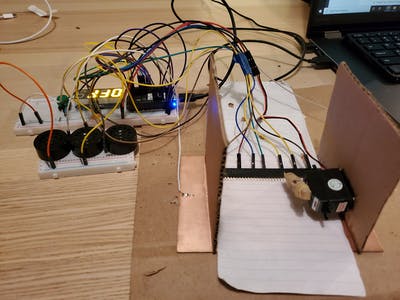
2. Each hole is detected in the following way. First, 2 wires are soldered to each end of a copper plate so that it can be connected to ground. Then, 7 wires are placed on top of the copper plate; these wires are connected to their own analog-in pin on the PocketBeagle (one for each note: A, B, C, D, E, F, G). The hole-punched paper is passed through on top of the copper plate, and under these wires; when there is paper between the copper plate and these wires, then the value read by the analog-in pins will float up and down randomly. When there is a hole, the wire will momentarily be in contact with the grounded copper plate, and hence the analog-in pins will read a 0 (or somewhere close to that).
Hence, all you have to do is feed paper onto the copper plate, press the button to start, and watch the music start playing!
Preliminary Diagrams and Planning
Before beginning to put the project, together, I first made a list of what features I wanted the music box to have:
1. Multiple speakers to play multiple sounds at once
2. An on/off button
3. A servo to drive the paper
4. An LCD display to give the status of the music box
These are all visualized in the block diagrams below:
Note that there are only 6 wires connected to analog in pins, whereas earlier, 7 pins were mentioned (one for each note between A-G). Unfortunately, since the PocketBeagle only has 6 AIN 1.8V pins, one of these notes had to be left out.
The actual wiring of all of these components can be seen in the Fritzing schematic below:
Build Instructions: Hardware Components
Speakers
The music box includes 3 speakers, which means that up to 3 notes can be played simultaneously by the music box. This is depicted below:
One end of each speaker is hooked to ground, while the other is attached to a PWM output. In particular, I used the PWM0-A, PWM1-A, and PWM2-B pins on the PocketBeagle. This worked out fine, except for one small issue: for some reason, the the PWM0-A pin on my PocketBeagle is unable to output a signal at a frequency other than exactly 400 Hz. Having looked online, this seems to a very uncommon issue, with no clear resolution. Given that, I’ve decided to leave in this 3rd speaker with the expectation that anyone else who tries this project is unlikely to run into the same issue.
Also note the fact that we only have 3 speakers means only 3 notes can be played at a time. In the event that more than 3 notes are read by the music box (ie. due to too many holes being punched in a row), the code is set up to randomly choose 3.
4-Digit7-SegmentDisplay
The
purpose of the 4-digit 7-segment display is so that the user can know if the device is on or off. The display will show "off" when the music box is off, and "go" if the music box is on ("go" is chosen instead of "on" because the 7-segment display cannot display an "n"). In my setup, this display was wired to the I2C1 pins on the PocketBeagle, with the appropriate pull-up resistors included for the SDA and SCL lines, as well as power and ground hooked up as appropriate:
Button
As mentioned above, a button was used to allow the user to turn the music box on and off:
One terminal of the button is connected to both a pull-up resistor as well as GPIO 59 on the PocketBeagle, which has been configured into an GPIO_IN pin in the code below. The other end is connected to ground. Hence, the GPIO pin will read a "1" when the button is not pressed, and a "0" when the button is pressed. Hence, the code can simply detect for a "0" to see if the button is pressed.
ContinuousRotationServo
The continuous rotation servo, as mentioned above, serves as the "crank" that moves the paper through the page. This was wired up as typical, with the "signal" pin of the servo wired to the PWM0-B pin on the PocketBeagle. The rate of rotation is fixed, at 400Hz and duty cycle of 25.
Beyond just the hardware component, the servo was wrapped in rubber bands to make sure that it can actually "catch" and move the paper while rotating. This is displayed below:
HeaderPins
The most important part of the whole setup are the actual wires that detect notes! Each of these wires was connected to a different Analog-In pin; in particular, the pins used were P1_19, P1_21, P1_23, P1_25, P1_27, P2_36. These wires were connected to header pins just so that they could easily be held in place. This is depicted below:
(Note that there are 7 wires in the pictures, whereas only 6 are actually connected to the PocketBeagle — the 7th extra wire was left in mostly just to preserve spacing).
As mentioned before, since these wires are not connected to anything most of the time, the simply float. However, when they come into contact with the grounded copper plate, the Analog-in they are connected to will read 0!
CopperPlate
The final component is simply a grounded copper plate. The copper plate used was the same kind you might find being used for a PCB mill. I soldered a wire to each side of the copper plate, and then plugged in each of these wires to ground on the PocketBeagle:
Physical Assembly of Music Box
After connecting all the electrical components, it’s time to assemble everything into the actual music box!
First, take the copper plate, and superglue two piece of cardboard to form the sides of the music box, close enough so that the header pins can be securely wedged between:
Then, superglue the continuous rotation servo to one side of the music box, at the exact height so that the servo "arms" just barely touch the copper plate:
And that’s it, we’re done!
Code Setup
1. Use the latest PocketBeagle image from BeagleBoard.org
2. Download this project_01 folder from
this repo
, unzip, and then move into the Cloud9 IDE on your own PocketBeagle
3. Ensure you have Python as well as the Python AdaFruit_BBIO package installed locally. If not, the steps to execute are:
sudo apt-get install build-essential python-dev python-setuptools python-pip python-smbus-y

sudo apt-get install python-pip

sudo apt-get install python3-pip

sudo pip install Adafruit_BBIO
4. Navigate to the project_01 folder, and change the permissions on the run script
chmod 755 run
5. Use Chron so that program will run on autoboot in the following steps
- Navigate to your local cloud9 folder
- Type "mkdir logs"
- Type "sudo crontab -e"
- Add to the end of the file:
@reboot sleep 30 && sh <full path to 'run' script> > /var/lib/cloud9/logs/cronlog2>&1
6. Reboot the PocketBeagle, and the code will auto-run after 30 seconds of waiting!
Operation Instructions
1. Hole punch paper to obtain desired song
2. Feed the paper into the music box, far enough in so that part of it lies under the continuous rotation servo
3. Turn on PocketBeagle, and wait for 30 seconds for the program to auto-start up
4. Press the button to turn on, and enjoy the music!
Here’s a video demonstration (note that the header pins need to be in pretty good contact with the copper plate for this to work; my header pins were kinda warped from experimenting with the setup too much, so in this video I have to push them down myself):
Next Steps/Future Improvements
A few notes about the limitations of this project that are evident from the video
- Sometimes, the pins linger over a hole for too long, and this registers as multiple notes
- When multiple notes are registered together too quickly, this creates a buffer in the backlog for the speakers, which creates a delay between the music box and the actual sound being played
These would be the two main fixes this project needs. Other changes I’d want to make for this project, moving forward, are:
- Create a more robust housing for the device (either using a laser cutter, or 3D printer)
- Reduce the delay between the time the music box detects a hole, and the time the speaker is played
- Find a way to incorporate more notes (i.e. include notes with accidentals)
- Add a volume control
- Add a way to control the speed of the continuous rotation servo
Acknowledgements
Finally, a special thanks to Professor Erik Welsh (
https://www.hackster.io/welsh
) for all the help on making this project possible!
Comments are not currently available for this post.