Categories: Intermediate
Motivation:
All golfers know that practicing putting can get a little boring and it is easy to lose focus. Additionally, it is common knowledge that the speed of a putt is much more important than the direction of the putt. Therefore, I decided to create a putting aid that is fun, interactive, and will help you dial in your speeds on the green.
I spent some time reading up on various golf science articles that discuss the optimal speed at which a ball should enter the hole. I found that a ball entering the hole at around 70 cm/s will accurately hold the line of the putt and stop approximately 1-2 ft behind the hole if the putt misses the cup. Moreover, this tool registers putts rolling between 60-80 cm/s as the ball enters the hole as a perfect putt. Putts rolling faster than 80 cm/s are read as too fast, and putts rolling slower than 60 cm/s are read as too slow.
Implementation:
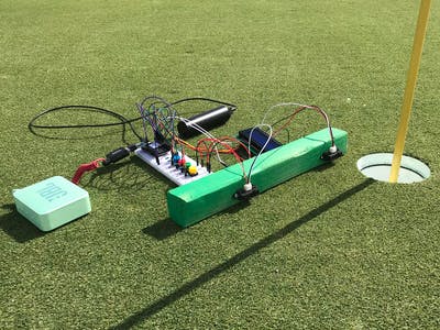
In order to successfully use this putting aid, the apparatus should be placed along the line of the desired putt just to the left of the cup on the putting surface. This tool works best for level, straight putts that are between 4-10 ft from the hole. The PocketBeagle must be supplied with a 5V of power. The program takes 30 seconds to boot up upon supplying the power. The yellow button can be pressed to begin recording putt speeds. The user must wait for the audio queue, “Ready for putt” before hitting each putt. The tool will record the speed of each putt, display it on the screen, and provide audio feedback based on the speed of the roll. This functionality is shown in the video below.
Additionally, if the user presses the green button on the breadboard, the LCD screen will display the putt speed history, with the first putt recorded as #1 on the list. The red and blue buttons can be used to toggle up and down on the list. All putt speeds are in cm/s. The yellow button can be pressed again to switch the mode back to recording putts. This operation is shown in the video below.
Press the power button on the PocketBeagle to turn off the device.
Set Up/Build Process:
Audio:
The first program functionality I attempted to tackle was the audio. I decided to use aplay, an audio file player for the ALSA sound card driver. I downloaded the player with the code below.
pip3 install aplay
I used a generic online .wav file recorder to record the various audio files I wanted to integrate into the project. I simply downloaded those files into the PocketBeagle’s file directory. The .asoundrc file and asound.conf file needed to be altered slightly in order for the aplay function to work. The default speaker system had to be changed by pasting the code below into both files.
pcm.!default {

        type hw

        card 1

}


ctl.!default {

        type hw

        card 0

}
I had to comment out the original default in the asound.conf file. In order to actuate these audio files within the program, the os function must be imported and utilized. The format of this is shown below.
import os

os.system("aplay <insert full file path here>")
The speaker was connected to the PocketBeagle with a miscroUSB adapter in the USB1 pins. A microUSB to USB adapter was attached to the first adapter. Then, a USB to auxiliary adapter was attached to the second adapter. The speaker then connected to the auxiliary jack. This set up is shown below.
Sensors:
The next portion of the project that I completed was wiring up and confirming the functionality of the 2 IR Distance Sensors. Both sensors are supplied 5V of power and operate as GPIO inputs. The first sensor is connected to pin P2_04 (gpio58) and the second sensor is connected to pin P2_06 (gpio57). I first tested their functionality by checking their input values, making sure they changed from 0 to 1 when something was placed in front of each sensor. I then decided on the distance that I wanted the sensors to be from each other, 17.75 cm, so I could complete the speed calculations in the code. The time at which the first sensor is activated is recorded, then the time at which the second sensor is activated is recorded. Then the speed calculation is performed and the LCD display shows the speed of the putt and the speaker plays the audio clip associated with the speed range of each putt.
In order to secure the sensors in their proper position, I decided to mount them to a piece of wood. I first spray painted the piece of wood green and marked where the sensors needed to be mounted.
I then secured the sensors in place using small wood screws. And the sensors were then ready to go!
LCD
Display:
After completing the sensor set up, I decided to work on the display function of the device. I decided to solder an I2C onto the 20×4 Character LCD Display in order to simplify the wiring.
I then inserted jumper wires into the I2C backpack’s ground, power, DAT, and CLK pins and connected them to the breadboard. The DAT and CLK connections received 1k ohm pull up resistor connections to the 5V power supply as well as additional jumper wire connections to the PocketBeagle. The CLK wire from the I2C backpack fed into pin P2_09 (SCL I2C1) on the PocketBeagle, and the DAT wire fed into pin P2_11 (SDA I2C1).
Next, I downloaded the Adafruit character LCD library using the command-line code below.
sudo pip3 install adafruit-circuitpython-charlcd
The code below helps to initialize the LCD screen and simplify the necessary code for achieving desired display functionalities.
import board

import busio

import adafruit_character_lcd.character_lcd_i2c as character_lcd

i2c = busio.I2C(board.SCL, board.SDA)

cols = 20

rows = 4

lcd = character_lcd.Character_LCD_I2C(i2c, cols, rows)
I had to adjust the contrast of the screen on the I2C backpack in order for the text to be visible on the display.
I then integrated simple display commands into my code to allow the screen to show the speed of individual putts in real time, reset to the "Ready" screen before each putt, and display the history list of all recorded putts. These functions are depicted in the videos above.
Buttons:
The last step in completing the assembly of the Putt Speed Tracking device was integrating the four push buttons. All four buttons are wired to the PocketBeagle as GPIO inputs and have 1k ohm pull up resistors connected to 3.3V power. The first button that I added to the breadboard was the yellow button that initiates the record function of the device. This button is connected to pin P2_02 (gpio59). I then added the green button that switches the devices mode to the history display. This button is connected to pin P2_08 (gpio60). This button also triggers an audio clip that announces the change in mode. Next I wired the red and blue buttons, the toggle buttons that allow users to scroll up and down through the speed history display. The blue button scrolls down the list of putt speeds, and the red button scrolls back up the list. The red button is connected to pin P2_10 (gpio52), and the blue button is connected to pin P2_19 (gpio27). The image below shows the set up of the four buttons.
Code:
The code consists of three files: the main code, a run script, and a configure pins file. The main program defines three functions: a record function, print history function, and toggle history function. These functions consist of while loops that contain numerous if statements that wait for certain events, ie. button presses or sensor activations. The program culminates into a main while loop that again, waits for certain button presses to call the various functions, yellow button press to initiate the record function and a green button press to display the history.
Concluding
Remarks:
This project was super fun to make! The code is pretty straight forward and concise and the device works super well. I look forward to playing around with the audio files and maybe having the speaker crack certain jokes depending on speed of the putt. Thank you Professor Welsh for helping me along the way and showing me how fun Python and embedded systems can be! I look forward to continuing to use Python and pursue projects like this outside of the classroom.
Comments are not currently available for this post.