Categories: Intermediate
Introduction:
I wanted to make my own remote car where I would be able to control it from my phone. I wanted a project that would incorporate both coding and hardwarde design.
Overview:
I initially started this project thinking I would only be using a PocketBeagle, but I soon realized that I would need to use an Arduino to control my BLE module. I used the Arduino to control the BLE module because it already had a library in Arduino to control the car. The BLE module allows you to control your RC car from a phone app, Adafruit Bluefruit LE Connect, under the controller tab. After the RC car is powered by external power sources, you will be able to drive the car around using the arrow buttons.
Hardware:
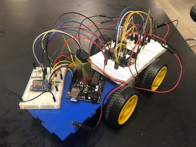
As stated earlier, this RC car uses both the PocketBeagle and the Arduino to control the motion by an app on your smartphone. In addition to the two microprocessors, I used an Adafruit Bluefruit LE SPI Friend module, Dual H-Bridge Motor Driver (L293D), four 4.7k ohms resistors, four 10k ohms resistors, a 9V batter, 6x AA batteries, and a 5V external battery charger. For the car, I used a Spark-Fun Multi-Chasis 4WD kit. In this kit, I received the main frame for the car, four motors, four wheels, and battery holder.
Fritzing Diagram:
Since I was not able to find the Bluefruit LE SPI Friend Module on Frizting, here are the connections that need to be made in order for the code to align with hardware. The BLE is wired to the Arduino, since the Arduino has already been wired to the PocketBeagle.
- SCK is connected to PIN 13
- MISO is connected to PIN 12
- MOSI is connected to PIN 11
- CS is connected to PIN 8
- IRQ is connected to PIN 7
- RST is connected to PIN 4
Since the car has four possible directions/movements, I had the Arduino connect using four gpio pins, where it is in an input onto the PocketBeagle. In order to accomplish this project, I had to use an existent library: Adafruit Bluefruit LE nRF51 (
https://github.com/adafruit/Adafruit_BluefruitLE_nRF51
). Inside that folder, I use the controller library; the only changes I made to the library is adding the connections to the PocketBeagle.
In the setup part of the Arduino Code in Controller, I added the pins that control the movement and designated them as outputs because they will be inputs on the PocketBeagle. They are also initially set as LOW, and will be HIGH when the button on the app is pressed.
In the loop, I set the pin values as HIGH.
This is the section of the code that will set the pin as a HIGH or LOW based on if the buttons are pressed.
Case 1, which is the number 1 on the button, is the fail safe stop; therefore, if the button 1 is pressed, all pins are set to a value of LOW.
Case 2, 3, and 4 do not have an if statement because those buttons are not being used.
Case 5 is the up arrow, meaning if pressed, the RC car will move forward and pin 6 will be set on HIGH.
Case 6 controls the down arrow, which means that the car will move backwards.
Case 7 and 8 control the direction of the RC car to the right or left, respectively.
GAME PLAY:
In order to control the RC car, you need to download the app and connect to the Adafruit Bluefruit. By connecting to the Bluefruit, you will then be able to select
Controller
as the tab to enter, where you will end up with a screen similar to the Figure above titled
TheControlButtons.
From here, it is very similar to controlling other RC cars.
Directions:
The Up Arrow allows for forward motion; the Down Arrow allows backward motion. The arrow pointing to the right, changes the direction of the car to the right; the arrow pointing to the left, changes the direction of the car to the left.
Future Upgrades:
In the future, I hope to use buttons 2, 3, and 4 for varying speeds and controls. In addition to enabling those buttons, I need to make a contained for all the breadboards and wiring that will make the RC car more user-friendly. With more time, a library for the BLE module may be made that will allow it to connect to the PocketBeagle directly rather than using an Arduino.
Comments are not currently available for this post.