Categories: Intermediate
About
The main goal of the project was to create a way to check the temperature of an ambient environment, display that information, and find a way to reduce that temperature. Currently, I live in a poorly ventilated dorm room where I often get stuffy. Checking my phone for the temperature is not helpful since the data is shows is collected from the temperature outside, rather than inside. I would like to know the temperature in my room so that I could know whether it would be worth it to open the windows, especially when I am laying in bed. Finally, what good is knowing the temperature and not being able to do anything about it? Not to mention this project is associated with a class I am taking so I might as well.
My vision for the project was a completely independent device that does not need internet connection to operate. I am on my computer often enough in my room, that is to say almost all the time, such that I would not mind connecting it to a computer. I would like the project to operate in the following manner: turn on the device by pushing a button already present on the PocketBeagle
I chose to use the PocketBeagle because it was the only available microcontroller I had and because it satisfies all of my project’s requirements. Next, I searched for a fan that could operate with a 5 Volt input. This was difficult since I found that many computer fans operate with a 12 Volt input, which would ruin my PocketBeagle if I used it. Ultimately, I found a fan that met my needs, the Noctua NF-A4x20 5V PWM, Premium Quiet Fan, 4-Pin.
Next, I looked for a sensor that could measure temperature. For simplicity, I chose to use a digital sensor that could operate between 3.3-5 Volts since the PocketBeagle has was the most readily available micro-controller to me and it could satisfy all the requirements of my project. After some searching, during which I found many different analog sensors, I found the Adafruit Si7021 Temperature & Humidity sensor. Though it does a little more than what I need it to do, it meets my technical requirements while still being easy to operate. It also operates at 3.3V, great for the PocketBeagle!
The last piece of hardware that I specifically needed to buy that I could not find around the Oshman Engineering Design Kitchen (OEDK), Rice University’s maker space, was a screen that could display the ambient temperature. I did not really have many requirements for this aside from that it needed to be able to display text. I was able to find such a screen in the 2.8" TFT LCF w/Touchscreen, also produced by Adafruit. It is also quite large so I would be able to see its output while normally sitting. As someone who wears glasses, this is very useful! My other components were simply breadboards and jumper cables that I found around the OEDK and/or were provided by my professor.
Wiring
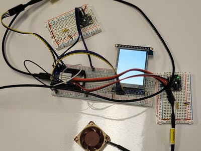
My next step was to determine the proper pin placements to wire the entire device together. Fortunately, I was able to soldering the pins onto my PocketBeagle correctly about a month beforehand, so physically connecting the PocketBeagle to my first breadboard was not difficult. The difficult part was figuring out where each of the jumper wires were supposed to go with regards to the hardware and on what pin they went. I am very fortunate to have had the help of my professor, Erik Welsh, when doing the necessary wiring. For more details on the pin orientation, please see the information directly below.
Fan 1Connections:
PWM -> P1_36
TACH -> P1_33
GND -> P1_22
VOUT -> P1_24
Fan 2Connections:
PWM -> P2_1
TACH -> P2_4
GND -> P2_15
VOUT -> P2_13
Temperature & Humidity Sensor1Connections:
GND -> GND
VIN -> 3.3V
SCL -> P1_28
SDA -> P1_26
Note:
1k Ohm pull up to 3.3V for SCL
Note:
1k Ohm pull up to 3.3V for SDA
Temperature & Humidity Sensor1Connections:
GND -> GND
VIN -> 3.3V
SCL -> P2_9
SDA -> P2_11
Note:
1k Ohm pull up to 3.3V for SCL
Note:
1k Ohm pull up to 3.3V for SDA
LCD Display Connections:
CLK -> P1_8
MISO -> P1_10
MOSI -> P1_12
CS -> P1_6
D/C -> P1_4
Note: Circuit is completed by GND –> P1_16 and VOUT –> P1_14
Both temperature and humidity sensors were attached to separate, smaller breadboards due to space restrictions in the main breadboard.
Some pictures of wiring as follows:
Coding
Once everything was wired, I began to write my code. I wrote it right on the PocketBeagle in Cloud9. To operate the temperature sensor, I had to download one library, listed below:
- Adafruit Si7021:
https://github.com/adafruit/Adafruit_CircuitPython_SI702
First, the PocketBeagle must be connected to the internet so it can download several additional libraries on its own, which will take about 15 minutes in total.
For coding, I chose to use Python because that was the language that Adafruit offered the most support in for its libraries. I began by coding the fan. Fortunately, I did not need to download any specific libraries in order to get the fan’s hardware to operate properly. However, I do need to be able to import Adafruit_BBIO.[pin type] for both GPIO and PWM pins, since the fan is a PWM fan. Afterwards, I began to attempt to code the temperature sensors. It was tough trying to figure out how to code for the pins to specifically use the I2C protocol, but that is all that is needed to code for the temperature/humidity sensor. Finally, I needed to code for the LCD screen. By following the tutorial provided by Adafruit, I was able to get text to show up once. However, I have not been able to replicate this in the timespan of this project.
Ultimately, I will acknowledge that I was unable to get the code fully completed in time, though I have been working on it since not only for personal development, but because I want to see this project to completion.
Video
The video only shows the component(s) that were successfully coded.
Dedications
- Erik Welsh, my professor, for provided a ton of guidance throughout this project and helping me scope it out properly
Future Goals
- Better integrate system as a whole
- Integrate the LCD screen into the system
Comments are not currently available for this post.