Categories: Advanced
Riding in Adelaide especially during night can be a hazardous activity. You have to share the road with cars and pedestrians, staying safe from the former and keeping the latter safe. Avoiding pedestrians requires vigilance from the cyclists, but the attention of cars has to be drawn with bright lights. Often due to circumstances you might need to ride in the middle of the lane or cut across lanes to make a turn. During the day these activities are indicated with a hand signal, I made this project to translate those to bright lights controlled by your motion and muscle activity to obvious signals during the night.
The controller used in this project is
Myo Armband
– it contains a 6 DoF IMU and 8 EMG sensors for muscle activity. The controller communicates to the BeagleBone via a
BlueGiga BLE dongle
, this appears as /dev/ttyACM0 on debian based images. The raw data from the sensors is processed using Scikits Learn and an
NN-classifier
to interpret the rider motions. The turn and stop activity is then passed over to a realtime controller (either the
BeagleBone’s native PRU
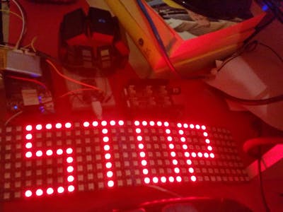
or an external microcontroller like the Teensy) to drive a
WS2812B LED matrix
.
The BeagleBone Green is modified to add a JST connector to activate the on-board battery charge management system to use a Lipo for poweing the bike lights according to
this how-to
. See the images below for details of this modification.
The whole system is wearable and battery powered. The LED matrix is stiched onto a high-vis jacket, a must for any night time riding and the Myo is placed around the fore-arm before starting the ride. Here is a video of the lights in action linked to gestures.
The Details
Install git on BeagleBone Green and sync the date using
ntpdate
. Then checkout my repository.
git clone

https://github.com/whatnick/myo-raw
Plug the Myo Blue Giga receiver in and check that it is recognised
lsusb
There should be 3 usb devices. The BeagleBone Green may need to be powered over USB instead of battery for the USB hub to power up and recognise the module.
Install the dependencies for myo-raw.
sudo pip install -r requirments.txt
The myo-raw can also be installed under Windows or any other desktop environment to stream the data from the BBG and display it remotely.
Run myo_raw_osc with the following command to stream data to remote server, print locally and send results from EMG sensor to external LED panel controller (in my case the Teensy, however I am also experimenting with the PRU’s)
screen -dmS myo python myo_raw_osc.py -v 1 -s 1 -d [x.x.x.x,7110] -c 2
This will output controller codes to the Grove UART port /dev/ttyO2 to the display driver in sync with arm motion. A bit of looking at the experimental data and tweaking of the classifier may be needed to get it set to you movement patterns.
That’s it for the setup on the BeagleBone Green in the non-PRU mode. For the Teensy, clone the git repository as below.
git clone

https://github.com/whatnick/Beagle_Pixel
Install the Teensy add-on for the Arduino IDE as described
here
and upload the code to the controller. The LED matrix data pin is connected to pin 2 of the Teensy and the BeagleBone UART is connected to Hardware UART1. I power the LED matrix from the 3.3V output of the Teensy rated at 100mA, this allows safely connecting the 3.3 output signal to this particular matrix. Larger matrices may require buffer IC’s and separate power supply. The BBG 5V system pin is connected to the VIN pin of the Teensy for power supply off the battery/USB OTB connected to the BBG.
Custom Cape
Having a second microcontroller (the Teensy) while 2 PRU’s on the BeagleBone are unused is a bit of a waste. So I deployed a custom cape typically used for building Christmas lights. The
cape kit
was purchased in South Australia from a local designer.
This cape works with
Falcon Player
(FPP) or
LedScape
. I ended up flashing FPP to the BeagleBone then running LedScape on it. To run LedScape, simply clone it from git and follow the install instructions.
git clone https://github.com/Yona-Appletree/LEDscape
To run LedScape automatically on start-up install it as a service and edit the config file to allow 256 LED’s. The config file found at:
https://github.com/Yona-Appletree/LEDscape/blob/master/ws281x-config.json
is edited to include:
"ledsPerStrip": 256,
The OPC (Open Pixel Controller) server can now control the display as shown below:
The code for driving this display is a fusion of python opc-client code and the myo-raw library used above. It is available in my repository
here
.
That is all for the set-up of this simple but very useful project.
Comments are not currently available for this post.