Categories: Beginner
The Clock
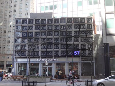
Today we will be making a large digital clock. The finished dimensions will be about 45 feet tall and 50 feet wide.
Below are concise step-by-step build instructions meant to guide you though the actual construction without any fluff. For insight into choices, challenges, and details, be sure to read the extensive FAQ at the end.
Step #1 – Cut Some Plastic
Inside each digit there is a self-contained panel that holds all the electronics.
Each panel is built onto a sheet of polycarbinate plastic which typically comes in 4’x8′ sheets. We will cut these sheets down to 1 meter by 1 meter squares using a circular saw and a straight edge…
It is a good idea to leave the protective plastic on until we are ready to install the panels into their final positions to protect from scratches. It is also a good idea to run a vacuum along the ends of the channels to clean out all the plastic chips left over from sawing.
Step #2 – Mount the LED strips
We are going to use standard WS2812B (a.k.a. "NeoPixel") RGB LEDs for our pixels. The ubiquitous 1 meter long strips with 60 individual LEDs on each strip are perfect for our project, and we will will need 30 of them per panel (2,400 strips in all).
The easiest way is to pull the strips into the channels inside the panels. To do this, I made a little puller tool out of a coat hanger and a loop of solid wire…
I push the puller though the channel from one end of the panel, pass the connector at the end of the strip though the loop, and then carefully pull the strip back though the channel…
We are going to fill the middle 30 channels with LED strips, and we are going to run the strips in sets of 5- so 5 going right to left, then 5 going left to right, and so on. It goes very quickly once you get the hang of it and you can do a whole panel in just a few minutes.
Click all the connectors together so you end up with 5 long interleaving strings of LEDs winding back and forth up the panel.
Now is also a good time to connect all the power lines. I like to use ScotchLok splice connectors since they are fast, cheap, and reliable. Since all the strips have their power leads connected together though the click connectors, it is not necessary to tie the power lines into every strip. As long as no pixel is more than 2 meters away from a power lead then everything will be fine. I also like to use two separate pairs of power feed wires to balance the load.
It is very important to use thick wire for the power feeds!
These LEDs draw a lot of current. I once got lazy and used 18 gauge wire for the power feed and it only took about 5 seconds of full brightness for the power wires to get hot enough to melt though the plastic panel…
I’ve never had any problems with 16 gauge power wires, and these fit nicely though the ScotchLok connectors.
Finally, I like to put a little squirt of hot melt glue or caulk in each end of the channels just to make 100% sure those strips are going to stay in place forever.
When you are all done mounting your strips, it should look something like this…
Step #3 – Mount and connect up the power supply
Connect the two power feed pairs coming from the LEDs to the DC output terminals of the power supply. I like to use crimp-on spade connectors. You should also connect a barrel connector that we will plug into the BeagleBone later.
I like to put the supply down towards the bottom of the panel. This keeps the cord out of sight and the weight at the bottom gives the panel a nice balance and feel. I drill holes though the panel above and below the supply and lock it down with a couple of thick zip ties. It looks like something this…
Step #4 – Make the interface boards
We are going to make a couple of printed circuit boards that will make it easier to connect the LED strips to out BeagleBone Green controller.
The boards are all single sided and very low spec, so they are easily milled or you can send them out to any PCB house.
The boards connect together with a standard 10 pin ribbon cable.
Step #5 – Mount and connect the BBG
Plug the transmitter board into the BBG as shown here…
…and then connect the data and ground wires coming from the 5 LED strings to the terminal block on the receiver board. I try to keep the pairs tightly twisted as they travel from the strips to the terminal block to cut down on emissions…
I usually put the BBGs inside a case just to protect them from getting bonked or shorted during transport and installation. That said, the BBGs are pretty robust little computers and I’ve done plenty of installations using just the bare board with no problems so far.
I like to use zip ties though holes (just like we did with the power supply) to hold the controller onto the panel.
Plug the barrel connector coming from the power supply into the BBG also.
Step #6 – Power-up, program, and test!
Plug in the power supply and wait for the BBG to boot. You should see the power LED on the BBG light up.
Connect using the on-board Ethernet port and follow the instructions in the README to download the software to the internal flash memory.
Once the demo sequence starts you can check for dead pixels and bad connections. Note that you probably want welding goggles for this since these panels are brain-toastingly bright!
Once everything checks out, it is probably a good idea to let new panels burn in for a few months just to make 100% sure that all the pixels are good. It is so much easier to swap out an LED strip before the panel is installed in the clock!
Step #7 – Repeat 79 more times
We are going to make a total of 80 panels. 72 will go into the clock on installation day and then rest will remain onsite as swap-outs so that the clock can keep running long after we have gone.
Your finished panels should look something like this…
Note that this demo panel gets dragged around to be shown off, so it has U-channels on the sides to protect the wires on the ends form getting caught on stuff. It also has pretty labels for all the parts which are probably not necessary on panels destined to be locked away inside digit boxes.
Step #8 – Final details
Now that you have all 80 of your panels assembled and tested, all you need to do to complete your clock is…
- Find the carcass of a nearby long defunct De Harak clock.
- Convince the owner to let you install the new panels (best if you can find an enlightened landlord like
Rockrose
who loves the clock as much as you do!).
- Get all the appropriate approvals and permits.
- Build a scaffolding in front of the clock for easy access.
- Have a team of electricians rewire each existing digit box in the structure with a 15 amp mains power circuit and an Ethernet home run to a control box inside a nearby building.
- Insert your panels into the digit boxes and plug them in.
- Set the time correct timezone on the clock’s control panel.
- Remove scaffolding and enjoy!
FAQ:
Below is information that is not required to actually build a clock, so I left it out of the instructions proper. I did think it would be helpful to potential clock builders to help them understand choices and avoid potential pitfalls, so it is included here. I am also always happy to respond to additional questions and suggestions, and will update this section as new ones come in.
Q: Why use polycarbinate hurricane panels?
A: This material is durable, lightweight, and cheap and you can get these panels at most home center stores. The light weight is especially important when you are leaning over the edge of a bucket lifter 40 feet up with one of these panels in your hands. Ease of handling is also why the power supply and controller are mounted where they are – the low center of gravity makes the panels easier to maneuver.
Note that I’ve also experimented with perforated stainless steel panels. The idea was to bond the LEDs to the steel and let the metal act as a giant heat sink. Testing has shown this to be completely unnecessary with 60 LED/meter density strips, and the metal panels are much heavier and more expensive. If, however, you ever want to try to build a panel with 144 LED/meter density, then maybe steel is the way to go.
Q: Why WS2812B ("NeoPixel") strips?
A: When I first started building these panels, I used Phillips Color Kinetics pixels but these were 10x to 100x times more expensive for a given resolution and brightness compared to NeoPixels. They are also harder to buy, harder to physically work with, and Phillips is surprisingly jerky about letting you publish code that talks over their crappy KiNET protocol.
I’ve also played around with the new AP102 ("DotStar") strips, but for our purposes here we do not care about frame rates faster than the eye can see so we are just paying more for a strip that needs more wires.
There are so many companies now making WS2812B chips and strips that they have become untouchably cheap and easy to get. As long as you are careful bout picking your suppliers based on long-term testing, they can also be very reliable.
Q: Where should I buy my strips?
A: While I love buying
NeoPixels from Adafruit
, for a project this size we are going to have to go to the source: Alibaba. Quality and price can vary wildly, so I recommend ordering a couple dozen sample strips from a bunch of different vendors and then stress testing them for a few months before putting in your final order.
Q: Why did you use waterproof strips?
A: It is a sizing thing – these strips happen to fit perfectly into the channels, making for very fast assembly (important when you are making 80 panels!).
Q: Why do you only fill in the middle 30 rows?
A: The shadow mask on the digits overs over the rest of the panel, so no reason to waste power and LEDs to make light no one will ever see.
Q: Why 5 strings rather than one long string, or 30 short strings?
A: One long string would mean fewer connection wires, but has two downsides. Firstly, it would reduce our maximum refresh rate to about 20Hz, which is visible and not fast enough for any kind of temporal dithering. Secondly, if one lone pixels someplace in the middle were to fail, we would completely loose everything visually above that pixel in one big visual block.
We could make 30 short strings and get a 1.2KHz refresh rate, but because of
PWM jitter artifacts
, this extra bandwith is not actually useful. It would be nice to never lose more than a single row in case of a pixel failure, but 30 data wires and 30 ground wires running from strips to the controller are difficult to manage and connect.
Having 5 strings seems to be the sweet spot. It gives us a decent refresh rate, limits losses to no more than 20% of the pixels in distributed stripes in case of a pixel failure, and the spacing just happens to work out so the wires lay neatly without too much slack or stretch.
Q: Are there better options for mounting the strips?
Pulling the strips though the channels is best combination of fast, cheap, and reliable mounting method I’ve found so far. I also like that the strips are supported along their length so they are not stressed by thermal cycling. Keep in mind that we want these panels to last though decades of daily and seasonal temperature swings.
I have also experimented with mounting the strips on the face of the panels, which allows the use of lighter panels with smaller channels and also probably helps the LEDs run cooler because they are exposed to air convection.
I do not recommend using the adhesive backing that often comes with these strips. Even though it usually has "3M" or "3M 200MP" printed on it, I think it is unlikely that it is actual 3M tape because it does not stick well to either the strip or the panel.
Normal 3M double sided foam tape like you’d get at an office supply store seems to adhere well, but it is possible (but difficult) to pull the strips off so I’d be worried about it potentially failing after the long term thermal cycling.
If money is no object and you the absolute best mounting, you should use 3M VHB tape. This stuff is crazy. They use it for holding cars together. You will never ever get get a VHB bonded strip off a panel without destroying the strip and the panel. Unfortunately, it is prohibitively expensive or it would be my first choice for clock building.
I’ve also been testing various liquid applied adhesives and have promising results. So far the best performer has been a thin film of GE Silicone I, which is nice because it is also the cheapest of the pack. You can lay down the 30 ribbons quickly using a normal caulk gun, and then press the strips down using a roller (fingers get tried too quickly).
I’m hesitant to recommend this option until I have at least a year of aging and 100 thermal cycles of testing under my belt, but in the meantime let me know if you have any experience or options!
Q: Why the Meanwell HSP-300-5?
A: I am loving the Meanwell HSP-300-5 power supply for this project. It is just the right size for our panel. It is compact, has no moving parts, and feels like a tank. If you accidentally overload it, it peacefully shuts down and then magically resets when the overload is fixed.
Q: Is a 300 watt supply really enough power for this many LEDs?
A: The rule of thumb is that each pixel can draw up to 0.25W, so that would imply that we’d need a 450 watt supply. But pixels only draw that much power when they are displaying full brightness white, which is actually a combination of full brightness red, green, and blue all on at the same time. Our clock will never need to display more than one component color at full brightness at any given time, so our maximum power requirements drop by about a half (blue needs more power than red).
If we ever do want to show some bright white for a special occasion, we can either show 50% white (which visually is nearly as bright as 100% white), or we can show 100% white for a brief moment (like less than 1 second). The quick 100% white is nice to flash, strobe, sparkle, and lightning effects.
Q: What do the interface boards do?
A: These boards are purely to route signals and make hookups faster and neater – they do not do anything electrically. You could just as well poke the ends of the LED strip wires into the holes on the BBG header and glop some glue on there and everything would work fine (I know, I’ve done it lots of times!). Well, the boards are slightly better than that electrically because the signal lines and ground lines are alternated and run in parallel.
Q: Wait! Don’t you need level shifting buffers to connect those 5V LEDs to those 3.3V BB pins?
A: This is a touchy subject for some people. Listen, I know the haters are going to yell at me for connecting the LEDs directly to the BBGs output pins. They are going to insist that it is irresponsible to not use a buffer chip. That maybe so, but after connecting HUNDREDS of these things like this and having them run happily for YEARS, I am going to tell you that it is ok to be reckless with your signal levels here. If you just won’t be able to sleep without buffering your signals, I’ve also included a version of this board that has a proper buffer. Note that the chip on the buffered board needs power, so it has an extra row of pins to draw power off the BBG’s top header.
Q: Wait! Don’t you need 300 ohm resistors at the data input to the LED strings?
A: I know this is recommended best practice, but I so far have been unable to
find a definitive answer
as to why this resistor is necessary. Some say it is necessary to reduce ringing on the high impedance input pin, but then shouldn’t we also need a resistor on the input of every LED in the string rather than just the first one? Clearly everything works just fine without the intra-string resistors, and experience has shown me that everything also works fine without the resistors at the start of the string.
Q: Why BeagleBone Green?
A: BeagleBone is a great platform for our clock panels because is has (in approximate order of importance)….
- Functionality. The PRU subsystem is ideal for reliably and flexibly driving large numbers of WS2812B pixels.
- Low cost. The boards are relatively cheap.
- Mainstream availability. We can get as many as we need whenever we want them.
The BeagleBone Green has all these, and adds…
- Even better price. $20 per part matters when you are using lots of parts.
- No HDMI. We were paying for something we didn’t need and even caused some conflicts.
- Grove connectivity. Makes it super easy to add sensors so, say, we can log the temperature inside the a digit box.
Q: Shouldn’t we put a conformable coating on everything to protect from condensation?
A: I also assumed that these panels would be subject to condensation, but after inspecting the existing wiring inside 40 year old digit boxes, I can say that there is no evidence at all of condensation damage. My guess is that the small amount of heat generated by the panels is enough to always keep temperature inside the box above the dew point.
Q: What is the easiest way to test/burn-in panels before commissioning?
A; The software has a built in interface for running test patterns on the panels. The easiest way to access this is to plug in a USB Wifi adapter into the BB and then connect to it using your phone. This test screen should automatically pop up…
It is even smart enough to not let you run 100% white for long enough to overload the power supply.
You should probably unplug the Wifi adapter before installing the panel into the digit box or else people walking past the clock will be able to run the demo patterns on the digit -which actually can be fun to watch!
Q: Wait! There is more than one iconic Rudolph de Harak clock on earth?!?
A: There is only one, it is in New York city, and I got to it first. Sorry.
At the surface level, this project offers a proven system to make reliable, economical, robust, and simple lighting panels for large scale, long term installations. The individual panels can trivially be adapted to any size up to at least 4’x8′, and the system can scale to hundreds or even thousands of panels.
But at a higher level, I hope this project will inspire you to take on big projects- even projects that at first might seem
too
big. When I first started thinking about how to fix this three story clock, it seemed almost impossible considering I had never worked on anything that couldn’t fit on my desktop before. I had also never designed or built anything that needed to last for decades.
You can solve big problems if you…
- iterate by making lots of mistakes and learning from them
- ask for lots of help
- do real, hard, long term experiments rather than just guessing or trusting the general wisdom.
With each iteration and experiment you learn more, your design gets better, and you gain confidence that it will all (eventually) work right!
Comments are not currently available for this post.