Categories: Advanced
The idea of integrating electrical components as load bearing structural components of the mechanical design has technically been done before in multiple disciplines although we were interested in working on this project.
One prevalent feature of this electrical/mechanical mashup is that it reduces the amount of individual parts needed to put together a project. A driving force for us was to think of ways that we can limit ourselves in terms of sub-components because the thought of taking a PCB (or MCB, whatever it may be), adding the electrical components (including the motor and battery) and Bob’s-your-uncle was very appealing. We bypassed having to mount the electronics in an enclosure, worry about connectors, and also in some cases might have reduced the cost. We also thought it would be good practice for fast-paced board design in Altium and we had the Bantam/Othermill desktop PCB milling machines available to us.
We started the project out with a brainstorming session after the original plan was hatched to make sure everyone was on board and to decide major system choices that would steer (steering was one of those system choices) the whole design including how many batteries and what kind along with our propulsion system.
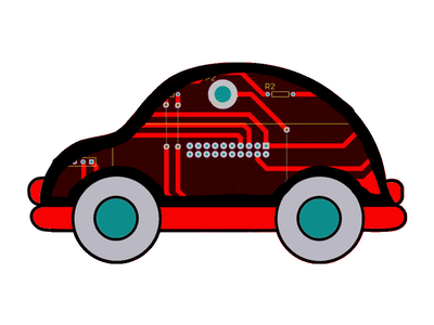
We eventually set the plan as pursuing a tank like propulsion system with two bi direction treads (wheels in our case however) that allowed us to stick with DC-motors only, as opposed to having the need of driving servos, and more importantly keep additional mechanical components out of the design and thus more of "printed circuit car" than not.
This decision then prompted us with another engineering choice. To achieve bidirectional control of the motors we could either make our own H-bridge circuit out of the base components or go with an integrated solution on a chip. Since we had some of those base components and felt up for challenging ourselves we started to investigate H-bridge circuitry along with setting up the initial codebase for our mircrocontroller (
MSP432
SimpleLink Dev Kit) and our single-board computer (
Beaglebone Black
). Both of the hardware choices were heavily influenced by the competition guidelines and available resources.
Saturday 09/29/18
The next day we had a late start but eventually got to prototyping what we had in mind for the H-bridge circuit on a breadboard. We eventually found out that we did not have the necessary components and it was not feasible to source and implement a home-brewed H-bridge. Although it would have been cool we decided to use the common L293d driver IC instead (and we learned a bit about N-channel MOSFETs along the way) and after making that decision we implemented the new circuit on a breadboard to verify that it would work. Which it did!
That night we spent a lot of time delving deep into the board design and farthing the code on both the ground station back end and the mobile station backend. We ran into a few hiccups with Altium but it gave us a chance to learn the parallel workflow between multiple developers.
In the end we had produced two boards with full features although time was limited for full testing.


Comments are not currently available for this post.