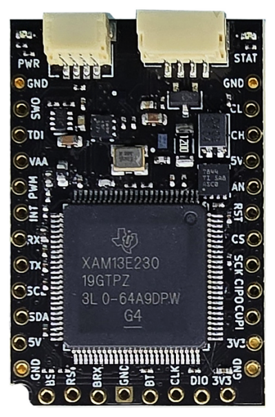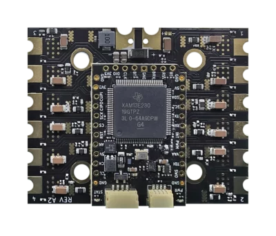
What is BeagleConnect QuadESC?
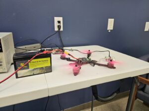 Put four motors under your control with open hardware you can inspect, modify and build upon. BeagleConnect QuadESC is a four-channel brushless DC motor-control board for robotics, drone propulsion and real-time control development. BeagleConnect Torque comes installed, combining a 200 MHz Arm Cortex-M33 processor with dedicated math and neural-network acceleration to coordinate four three-phase power stages.
Go beyond commanding motor speed. Each channel includes three-phase current sensing, phase-voltage sensing and a nearby board-temperature sensor. The feedback routes and dedicated PWM time base for each motor provide a hardware foundation for field-oriented control, synchronized measurements and custom control algorithms. Onboard CAN hardware connects your controller to a wider system.
BeagleConnect QuadESC brings the controller, power stages, sensing and regulated controller power together on a 60 × 48 mm PCB. Editable KiCad designs, firmware sources and detailed hardware manuals support learning, experimentation and custom system development within the BeagleBoard.org ecosystem.
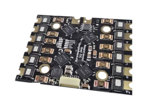
Build with BeagleConnect QuadESC
Explore coordinated robot drives, multi-motor mechanisms and drone propulsion, or study the relationship between switching waveforms, current measurements and motor torque. Each motor’s three phase-current inputs are distributed across three analog-to-digital converters, allowing firmware to sample that motor’s current triplet simultaneously. Four motors share those converters, with acquisition timing arranged by the application.
Use the flight-controller connection for command and reporting signals, or develop a CAN-connected controller through BeagleConnect Torque. The processor’s trigonometric math unit supports control calculations, while its TinyEngine neural-network accelerator provides a resource for application-specific fault and anomaly detection.
Factory ROM provides TI’s bootstrap loader. Load suitable application firmware before operating motors. Field-oriented control, DShot command decoding, telemetry and AI diagnostics depend on the firmware you install; match the application to your motors and connected controller. Programming and debug documentation includes TI XDS110 setup.